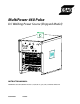
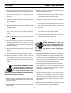
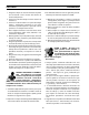
MultiPower 460 Pulse DC Welding Power Source (Shipyard Model) MIG PULSE POWER PANEL STANDARD A STICK 0 4 5 6 7 AMPS STEADY NO PROGRAM LIFT START TIG REMOTE WFS-IPM TEMP BLINKING WIRE SPEED OUT OF RANGE MIG PRESET 8 V VOLTS Auto Fan Fan will cycle automatically Multipower 460PULSE 9 Voltage (CV) Current (CC) Trim (Pulse) PULSE SELECTION AL-4000 STAINLESS STEEL EN-625 ERNiCrMo-3 AL-5000 .040 METAL CORE STEEL EN-67 ERCuNi .035 EN-60 ERNiCu-7 WIRE TYPE .045 .
Be sure this information reaches the operator. You can get extra copies through your supplier. caution These INSTRUCTIONS are for experienced operators. If you are not fully familiar with the principles of operation and safe practices for arc welding and cutting equipment, we urge you to read our booklet, “Precautions and Safe Practices for Arc Welding, Cutting, and Gouging,” Form 52-529. Do NOT permit untrained persons to install, operate, or maintain this equipment.
table of contents Section / Title Page 1.0 Safety Precautions . . . . . . . . . . . . . . . . . . . . . . . . . . . . . . . . . . . . . . . . . . . . . . . . . . . . . . . . . . . . . . . . . . . . . . . . . . . . . . . . . . . . 5 1.1 Safety - English . . . . . . . . . . . . . . . . . . . . . . . . . . . . . . . . . . . . . . . . . . . . . . . . . . . . . . . . . . . . . . . . . . . . . . . . . . . . . . . . . .5 1.2 Safety - Spanish . . . . . . . . . . . . . . . . . . . . . . . . . . . . . . . .
table of contents
section 1 1.0 safety precautions Safety Precautions 1.1 WARNING: These Safety Precautions are for your protection. They summarize precautionary information from the references listed in Additional Safety Information section. Before performing any installation or operating procedures, be sure to read and follow the safety precautions listed below as well as all other manuals, material safety data sheets, labels, etc. Failure to observe Safety Precautions can result in injury or death.
section 1 safety precautions 1. Be sure the power source frame (chassis) is connected to the ground system of the input power. 3. Welders should use the following procedures to minimize exposure to EMF: 2. Connect the workpiece to a good electrical ground. A. Route the electrode and work cables together. Secure them with tape when possible. 3. Connect the work cable to the workpiece. A poor or missing connection can expose you or others to a fatal shock. B.
section 1 safety precautions 5. WARNING: This product, when used for welding or cutting, produces fumes or gases which contain chemicals known to the State of California to cause birth defects and, in some cases, cancer. (California Health & Safety Code §25249.5 et seq.) 1. Always have qualified personnel perform the installation, troubleshooting, and maintenance work. Do not perform any electrical work unless you are qualified to perform such work. 2.
section 1 safety precautions 5. AWS C5.5 - "Recommended Practices for Gas Tungsten Arc Welding“ 6. AWS C5.6 - "Recommended Practices for Gas Metal Arc Welding"“ 7. AWS SP - "Safe Practices" - Reprint, Welding Handbook. 8. ANSI/AWS F4.1, "Recommended Safe Practices for Welding and Cutting of Containers That Have Held Hazardous Substances." Meaning of symbols - As used throughout this manual: Means Attention! Be Alert! Your safety is involved.
section 1 1.2 SEGURIDAD Safety - Spanish La escoria puede estar caliente y desprenderse con velocidad. Personas cercanas deberán usar gafas de seguridad y careta protectora. ADVERTENCIA: Estas Precauciones de Seguridad son para su protección. Ellas hacen resumen de información proveniente de las referencias listadas en la sección "Información Adicional Sobre La Seguridad".
section 1 SEGURIDAD 1. Asegúrese de que el chasis de la fuente de poder esté conectado a tierra através del sistema de electricidad primario. 2. Conecte la pieza de trabajo a un buen sistema de tierra física. 3. Conecte el cable de retorno a la pieza de trabajo. Cables y conductores expuestos o con malas conexiones pueden exponer al operador u otras personas a un choque eléctrico fatal. 4. Use el equipo solamente si está en buenas condiciones. Reemplaze cables rotos, dañados o con conductores expuestos.
section 1 SEGURIDAD 5. ADVERTENCIA-- Este producto cuando se utiliza para soldaduras o cortes, produce humos o gases, los cuales contienen químicos conocidos por el Estado de California de causar defectos en el nacimiento, o en algunos casos, Cancer. (California Health & Safety Code §25249.5 et seq.) 1. Siempre tenga personal cualificado para efectuar l a instalación, diagnóstico, y mantenimiento del equipo.
section 1 SEGURIDAD SIGNIFICADO DE LOS sImbolOs -- Según usted avanza en la lectura de este folleto: Los Símbolos Significan ¡Atención! ¡Esté Alerta! Se trata de su seguridad. Significa riesgo inmediato que, de no ser evadido, puede resultar inmediatamente en serio daño personal o la muerte. Significa el riesgo de un peligro potencial que puede resultar en serio daño personal o la muerte. Significa el posible riesgo que puede resultar en menores daños a la persona.
section 1 1.3 SÉCURITÉ Safety - French INCENDIES ET EXPLOSIONS -- La chaleur provenant des flammes ou de l'arc peut provoquer un incendie. Le laitier incandescent ou les étincelles peuvent également provoquer un incendie ou une explosion. Par conséquent : AVERTISSEMENT : Ces règles de sécurité ont pour but d'assurer votre protection. Ils récapitulent les informations de précaution provenant des références dans la section des Informations de sécurité supplémentaires.
section 1 SÉCURITÉ 1. Assurez-vous que le châssis de la source d'alimentation est branché au système de mise à la terre de l'alimentation d'entrée. 2. Branchez la pièce à traiter à une bonne mise de terre électrique. 3. Branchez le câble de masse à la pièce à traiter et assurez une bonne connexion afin d'éviter le risque de choc électrique mortel. 4. Utilisez toujours un équipement correctement entretenu. Remplacez les câbles usés ou endommagés. 5.
section 1 SÉCURITÉ 5. AVERTISSEMENT : Ce produit, lorsqu'il est utilisé dans une opération de soudage ou de coupage, dégage des vapeurs ou des gaz contenant des chimiques considéres par l'état de la Californie comme étant une cause des malformations congénitales et dans certains cas, du cancer. (California Health & Safety Code §25249.5 et seq.) ENTRETIEN DE L'ÉQUIPEMENT -- Un équipement entretenu de façon défectueuse ou inadéquate peut causer des blessures graves ou mortelles. Par conséquent : 1.
section 1 SÉCURITÉ SIGNIFICATION DES SYMBOLES Ce symbole, utilisé partout dans ce manuel, signifie "Attention" ! Soyez vigilant ! Votre sécurité est en jeu. DANGER Signifie un danger immédiat. La situation peut entraîner des blessures graves ou mortelles. AVERTISSEMENT Signifie un danger potentiel qui peut entraîner des blessures graves ou mortelles. ATTENTION Signifie un danger qui peut entraîner des blessures corporelles mineures.
section 2 description 2.0. Description This manual has been prepared for use by an experienced operator. It provides information to familiarize the operator with the design, installation and operation of the MultiPower 460 Pulse power source. DO NOT attempt to install or operate this equipment until you have read and fully understood these instructions. The information presented here should be given careful consideration to ensure proper installation and optimum weld performance of this equipment.
section 2 description The MultiPower 460 Pulse is a multi-process power source designed for Mig short circuiting, spray and pulse spray transfer (GMAW), flux cored (FCAW), Tig (GTAW), and stick (SMAW) welding and air carbon arc cutting/gouging (CAC-A) applications. Table 2-1 outlines the electrical and physical specifications. A. Power Source The power source is a constant current (CC) and constant voltage (CV), three phase, secondary chopper dc design with solid state contactor and control circuitry.
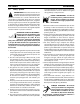
section 2 description C. Control Panel Description (Refer To Figures 2-2 & 2-3) 1. Fault Lamp The RED fault light on the MultiPower 460 Pulse front panel indicates a problem with set-up parameters. A "Steady-On" light indicates there is no program for the material and wire diameter selected. A "Blinking" light indicates the wire feed speed is out of the recommended range. 2. Temperature Lamp The TEMP lamp illuminates if an over temperature condition occurs within the MultiPower 460 Pulse power source.
section 2 description 5. Voltage / Current / Trim The Power Source Open Circuit Voltage is controlled with this knob when the WELD PROCESS selector switch is in the MIG position. The Mig open circuit voltage can be preset by pressing the PRESET button and reading the arc volts in the bottom digital display while rotating this knob. The weld current is controlled with this knob when the WELD PROCESS SWITCH is in the TIG or STICK position.
section 2 description 7. Preset Button Preset push button is used in conjunction with the VOLTAGE/CURRENT/TRIM knob to set the desired voltage / current. Preset switch is also used in the Pulse Mig mode to preset the pulse parameters by using preset wire feed speed as the intial setting for the “Off the Arc” feeder. 8. Standard / MIG Pulse Switch This switch enables the Mig pulse mode.
section 2 description D. Power Source Front View Description (Refer To Figure 2-4) 1. Power On/off Switch & Lamp The main power switch is located on the right front panel of the power source. This switch energizes the main transformer, control circuitry and illuminates the Power “ON” lamp. 2. Remote Control Receptacle This receptacle (J8) is provided for an optional 14-pin control cable from the optional remote pendant, Tig torch control or foot control .
section 2 description E. Optional Accessories 1. Remote Control Pendant (P/N - 0558002871) This pendant (Figure 2-5) provides remote output control and a MIG contactor closure switch to close the contactor making the output terminals “hot”. The PANEL/REMOTE switch on the MultiPower 460 Pulse control panel must be placed in the REMOTE position when using this accessory. Figure 2-5. Remote Control Pendant 2. Remote Control Options The options below (Figure 2-6) provide remote output control.
section 2 description 24
section 3 installation 3.0. Installation A. Location A proper installation site is necessary for the power source to provide dependable service. A proper installation site permits freedom of air movement through the unit while minimizing exposure to dust, dirt, moisture, and corrosive vapors. A minimum of 18 inches (46 cm) is required between the side and rear panels of the power source and the nearest obstruction.
section 3 installation C. Primary (Input) Electrical Connection This power source is a three-phase unit and must be connected to a three-phase AC primary power. It is recommended that the unit be operated on a dedicated circuit to prevent impairment of weld performance due to an overloaded circuit. Table 3-1. Recommended Sizes for Input Conductors and Line Fuses Rated Input @ 100% Duty Cycle Volts Amps Input & GND Conductor* CU/AWG 220 230 400 460 575 68 66 37 33 26 No. 6 No. 6 No. 8 No. 8 No.
section 3 WARNING installation The chassis must be connected to an approved electrical ground. Failure to do so may result in electrical shock, severe burns or death. REAR PANEL VIEW Figure 3-1. Typical Installation - User Supplied 3 Phase Fused Power Disconnect Box with Receptacle and Plug 1. 2. 3. 4. The primary power leads must be insulated copper conductors. Three power leads and one ground wire are required. Either rubber covered cable or conduit (flexible or solid) may be used.
section 3 installation ELECTRIC SHOCK CAN KILL! Before making electrical input connections to the power source, "Machinery Lockout Procedures" should be employed. If the connections are to be made from a line disconnect switch, place the switch in the off position and padlock it to prevent inadvertent tripping. If the connection is made from a fuse box, remove the corresponding fuses and padlock the box cover.
section 3 5. installation Figure 3-4 illustrates the input voltage terminal boards and the input voltage link connections. The particular voltages from which this power source may be operated are stated on the rating plate. The voltage links were factory set for highest voltage stated on the rating plate (460 VAC). If the power source is to be operated on another stated input voltage, the links must be reset for that particular input voltage.
section 3 installation D. Output Welding Connections (Secondary) The output connections are located on the front panel (Figure 2-4). The positive connection is located at the bottom left corner and the negative connection is located at the bottom right corner. Table 3-2 provides the recommended secondary cable output sizes. 1.
section 4 operation 4.0. Operation A. Wire Feeder Compatibility The MultiPower 460 Pulse power source is designed for use with “Off the Arc” or “Voltage Controlled” wire feeders. These types of wire feeders can be operated in either the CV (MIG) or CC (Stick) mode. The wire feed speed is always controlled from the wire feeder using the wire speed knob on the feeder control panel. The MP-460 Pulse can output either CV or CC power.
section 4 operation caution When the WELD PROCESS switch is moved to the TIG or STICK position, electrode becomes electrically “HOT”. Do not allow the electrode to contact ground potential until you are ready to make a weld. C. Tig Welding (Lift Start Tig) When the PROCESS switch is placed in the LIFT START TIG position, the MultiPower 460 Pulse is automatically set for CC (constant current) welding using the ESAB Lift Start TIG starting method.
section 4 operation caution When the WELD PROCESS switch is moved to the TIG or STICK position, electrode becomes electrically “HOT”. Do not allow the electrode to contact ground potential until you are ready to make a weld. D. Stick Welding When the PROCESS switch is placed in the STICK position, the MultiPower 460 Pulse establishes open circuit voltage (OCV) and output power is immediately available for welding.
section 4 operation caution When the WELD PROCESS switch is moved to the TIG or STICK position, electrode becomes electrically “HOT”. Do not allow the electrode to contact ground potential until you are ready to make a weld. E. Air Carbon Arc Gouging (CAC-A) - Constant Current 1. 2. 3. 4. 5. 6. Be sure the CONTACTOR “ON/OFF” switch on the lower left auxiliary panel is in the OFF position.
section 4 operation When the CONTACTOR switch is moved to the “ON” position, MP-460 Pulse output terminals and the cables connected to them become electrically “HOT”. Do not allow the cable to contact ground potential. caution F. Mig & Flux Core Welding Preset Procedure When the PROCESS switch is placed in the MIG position, the MultiPower 460 Pulse is set for CV (constant voltage) welding for use with “Off the Arc” or “Arc Voltage “ type wire feeders.
section 4 operation Note 5 When using the MP-460 Remote Pendant Control, place the PANEL/REMOTE switch in the REMOTE position. This will defeat the MP-460 front panel voltage control. Voltage can then be adjusted from the remote pendant Figure 4-6 Contactor Switch for "Off the Arc" wire feeders G. Pulse Mig Setup 1. 2. 3. 4. 5. Connect wire feeder to MultiPower 460 Pulse and set PANEL/REMOTE switch to PANEL position. Set the STANDARD/MIG PULSE switch to the MIG PULSE position.
section 4 operation H. Pulse Mig Welding using “Off the Arc” Wire Feeders The MultiPower 460 Pulse is designed to provide simple to use, high quality, preprogrammed pulsed Mig welding. The pulse parameters, such as pulse height, pulse width, background current and pulse frequency, are automatically adjusted by the MultiPower 460 Pulse depending on the WIRE TYPE and DIAMETER selected.
section 4 operation 1. Pulse Mig Arc Stability Many variables can affect the arc stability of pulse MIG welding. Some examples are: • • • • • • • • • Differences in shielding gas compositions Differences in weld wire chemistry Water vs. air cooled guns Base metal surface condition Tip-to work distance Variations on wire feed speed Wire feedability Long welding cables High resistance cables and connections When adverse conditions are present, the pulse arc stability is sometimes less than desirable.
section 5 maintenance 5.0. Maintenance And Troubleshooting A. Cleaning Periodically, remove the cover from the power source and blow accumulated dust and dirt from the air passages and interior components by using clean low pressure air. The frequency of cleaning required depends upon the environment in which the power source is used. It is imperative that all air passages be kept as clean as possible in order to allow adequate air flow to provide proper cooling.
section 5 maintenance G. IGBT Handling and Replacement WARNING STATIC ELECTRICITY can damage circuit boards and electronic components. • • Observe precautions for handling electrostatic sensitive devices. Use proper static--proof bags and boxes. What is ESD? A sudden transfer or discharge of static electricity from one object to another. ESD stands for Electrostatic Discharge. How does ESD damage occur? ESD can cause damage to sensitive electrical components, but is not dangerous to people.
section 5 maintenance G. IGBT Handling and Replacement (continued) Since IGBT gates are insulated from any other conducting region, care should be taken to prevent static build up, which could possibly damage gate oxides. All IGBT modules are shipped from the factory with conductive foam contacting the gate and emmiter sense pins. When mounting IGBT modules on a heatsink, certain precautions should be taken to prevent any damage against a sudden torque.
section 5 maintenance G. IGBT Handling and Replacement (continued) Insulated Gate Bipolar Transistor (IGBT) C2 E1 E2 C1 G2 E2 Set the VOM to ohms then check for continuity between all the legs of the IGBT. No continuity should be measured. Place the red probe to the Collector (C1) and the black probe to the Emitter ( E1). The VOM should read very high resistance or an open circuit. No shorts (continuity) should be measured. Repeat the steps on the second IGBT pair (C2 E2).
section 5 maintenance G. IGBT Handling and Replacement (continued) C2 E1 G2 E2 C1 E2 NOTE The power source should be more the 6 volts and less than 20. A 9 volt battery is common and works quite well. Once the IGBT is turned on, remove the power source and the unit should stay on. G2 C2 E1 E2 C1 E2 Short the gate leads (you can use your finger) to turn the unit off. This demonstrates the correct functioning of the unit.
section 5 maintenance H. Procedure for Checking Diodes Inspect the diode to determine if it is of the “ straight polarity “ or “reverse polarity” type. Refer to the following figure for typical marking of diode polarity. It is essential that a replacement diode be of the same polarity as the one removed.
section 5 maintenance Table 5-1. Troubleshooting Guide CONDITION ACTION Unit Inoperative READY/ ON Light is OFF Fan Does Not Run (READY Light is ON) No Output -- Fan Running No Output - STICK Position Meter Display is Blank Preset Does Not Function Ammeter Displays 760 Amps Limited Output or Low Open-Circuit Voltage Over Temperature Light is ON Erratic Weld Current A. No input power. Check main line (user’s) switch fuses -- replace if needed. B. Poor or improper input (terminal board) connections.
No Yes Yes No Is voltage at (PCB2) P1-1 to P1-2 = to 28 VDC Yes Figure 5-2.
Replace failed diodes No Is D1,2,3,4,5,6, good? Replace if failed (See Para. 5.H) No IS voltage at C1 + to C1 = 80 VDC No Is voltage at OTB+ to OTB- = 75 to 80 VDC Yes Verify Weld process in “Stick” Panel-remote in “Panel” Standard-Pulse in “Standard No weld power (Stick position) Power Light is On Yes Check and repair wiring Is Q1,Q2,Q3 good? Replace if failed (See Para. 5.G) Yes Figure 5-4.
Yes Replace Switch S4 Figure 5-6. PRESET Does Not Function Replace PCB1 No Does preset work when P2-11 and P216 (PCB1) are jumpered? Preset does not function (unit welds) Is OTB- + to OTB shorted No Is voltage at OTB + to OTB - = to 80 VDC No Repair short circuit No Is Voltage at (PCB1) P1-7 to P1-2 = > 7 VDC Yes Replace PCB-1 No Is Voltage at (PCB-1) P3-2 to P3-4 = > 7VDC Figure 5-7.
section 5 maintenance Over Temp light is on Was the Duty Cycle exceeded? Yes Allow time for machine to cool No Does voltage at P1-12 to P1-13 (PCB1) = 8VDC ? Yes Check resistance TS1 TS2 (Main Tranformer) TS3 (Inductor) TS4 OK open No Replace if switch is open Replace PCB1 Figure 5-8.
section 5 maintenance 50
section 6 6.0 Replacement Parts 6.1 General replacement parts Always provide the serial number of the unit on which the parts will be used. The serial number is stamped on the unit nameplate. 6.2 Ordering To ensure proper operation, it is recommended that only genuine ESAB parts and products be used with this equipment. The use of non-ESAB parts may void your warranty. Replacement parts may be ordered from your ESAB Distributor.
section 6 replacement parts 7 8 (behind control panel) 6 9 (behind control panel) 5 11 3,4 2 1 NO. QTY. REQ. 1 1 2 1 3 1 4 1 5 1 6 2 7 1 8 1 9 1 10 1 11 1 ITEM NO. 952219 951916 634515 951474 32385 950122 0558004931 951835 38246 38211 0558005655 DESCRIPTION Outlet 110V (Square) Connection Box Rcpt.
section 6 replacement parts 3 2 1 4 5 6 7 NO. QTY. REQ. ITEM NO.
section 6 replacement parts 3,5 2 1,5 4,5 7,5 MIG PANEL MIG PULSE LIFT START TIG PRESET POWER STANDARD REMOTE 0 WFS-IPM 4 A TEMP STICK 5 6 3 7 AMPS 2 BLINKING WIRE SPEED OUT OF RANGE STEADY NO PROGRAM V 8 9 1 VOLTS Voltage (CV) Current (CC) Trim (Pulse) PULSE SELECTION Auto Fan AL-4000 Fan will cycle automatically STAINLESS Multipower 460PULSE STEEL EN-625 ERNiCrMo-3 WIRE TYPE 1 2 3 4 5 6 7 8 9 10 .045 .052 1/16 WIRE DIAMETER 9,10 8 NO. AL-5000 .
section 6 replacement parts 3 4 2 1 5 6 5 NO. QTY. REQ. ITEM NO.
section 6 replacement parts 3 2 8 5 1 6 4 7 NO. 1 2 3 4 5 6 7 8 REQ. 3 3 1 1 1 1 1 1 QTY. NO.
section 6 replacement parts 3 2 4 6 1 5 NO. QTY. REQ. ITEM NO. DESCRIPTION SYMBOL 1 2 3 4 5 6 1 1 1 3 1 3 952938 951997 951085 0558002557 951940 0558002844 SCR 480V 18A Panel MNT Transducer Current SW THML D/T 176 15A 120V Q/D IGBT 600V/300A Capacitor 1.
section 6 replacement parts 3, 4 2 1 NO. 1 2 3 4 QTY. REQ. ITEM NO. DESCRIPTION SYMBOL 2 1 6 1 17280110 0558005169 672065 36091 Res WW Fix'd ST 100W 5% 100.
revision history 1. 2. 3. 4. 5. Preliminary release - 08/2004 Released - 09/2004 Added IGBT and diode test data in Section 5 and updated schematic package - 12 / 2004 Updated schematic package - 07 / 2005, del modified schematic 0558004922 made by J. Devito and replaced by schematic from smartteam per R. Eldridge & D. Griffin on 7/11/05. The 10/2005 revision updates the replacement parts section by adding p/n 0558005655, item 11, metal cap protection and illustration to the front view.
ESAB Welding & Cutting Products, Florence, SC Welding Equipment COMMUNICATION GUIDE - CUSTOMER SERVICES A. CUSTOMER SERVICE QUESTIONS: Telephone: (800)362-7080 / Fax: (800) 634-7548 Hours: 8:00 AM to 7:00 PM EST Order Entry Product Availability Pricing Order Information Returns B. ENGINEERING SERVICE: Telephone: (843) 664-4416 / Fax : (800) 446-5693 Hours: 7:30 AM to 5:00 PM EST Warranty Returns Authorized Repair Stations Welding Equipment Troubleshooting C.
1 2 3 4 Q7 ESAB ASY 38211 REV. H3 VR3 TP9 C55 IC17 IC14 Q5 9 P4 7 6 4 C1 WIRE SPEED REF. TP5 VOLTS REF. 1V/10V TP7 D2 IC1 D1 R3 D3 IC2 IC18 C3 + 3 Q6 8 2 1 IC13 C53 + C11 +15V C49 H4 MultiPower 460 PULSE (Shipyard Model) Control PCB PN-(8)38211 Sheet 1 of 3 + C41 C45 + TP2 + R129 IC12 C46 + HS1 R106 R107 + C38 C43 + R74 R72 C61 R187 D53 R179 + TP8 R102 R104 (+) Earc/10 C10 C4 TP1 COMMON H5 C42 R103 -15V (+) VREF.
1N4004 IC1 MC7915 2 C1 1000 uf -15v + TP3 +15v D3 1N4004 3 C2 + 100 uf 1 +15v 14 2 TP2 IC2 3 1K 2 LM317 R1 4.99K TP1 P1-2 3 Q3 R4 221 1 R2 4.99K C3 100 uf + R3 2N4401 RL1 .01 BR1 C4 D4 IC3 Q2 .01 P7-3 ZD1 1N5246 D FS20 UM6 C10 + S .01 - R16 R14 1M C11 15 DT INV E1 9 ZD2 R17 COMP E2 10 NIV INV 16 2 1N4732 1M .1 3W 3 8 C60 R25 .
I ARC (+) 1V/100A +15v I arc 1v/100A 14 11 13 (+) V/A REF. 100 30.1K 12 -15v R174 P3-1 33.2K P3-2 (-)1v/5v 20K R83 +15v 2 - 3 +IC11 4 4 R84 6 - 5 +IC11 VOLTS REF. 1v/10v 7 VOLTS REF. 1v/10v 100K P2-13 20K R89 P2-14 13 - 12 +IC11 4 IC10 68.1K -15v C41 + C40 10K R101 1K 9 R99 10 C42 R104 15K P3-7 3 15K R105 .0047 uf - 4 +IC12 9 8 40.2K -15v R107 100K R113 2K R112 3.01K -15v C43 R98 + 6 - 5 +IC12 R109 C58 .
+5v R4 P1 3.9K C3 35pf R5 10K C8 .1uf 6 R1 16 R3 18 270 10K R2 221K 17 C1 .1uf 13 1 2 3 7 R8 R6 RN1 7x150 OHM VDD MCLR OSC1 RA1 U1 RBO PIC16C711 (99513603) RB2 RB1 RB3 RA0 RB4 RB7 RB5 RA2 RB6 RA3 RA4 OSC2 VSS 6 1 7 8 9 14 25,21,16 2 13 24,20,15 3 12 4,8,13 4 11 2,7,11 10 5 10 1,6,10 11 6 9 27,23,17 12 7 8 28,22,12 15 X 24,20,15 +5v 4,8,13 +5v 2,7,11 R12 1,6,10 10K R15 10K 27,23,17 C5 .
J1-1 2 BR1 W04G 3- + 1 J1-3 + C1 1000uF 35V TP2 + C2 220uF 35V GND 2 J1-2 +15V U1 MC7815CT 1 IN OUT 3 4 TP1 U3 HPCL-2231 TP3 J1-5 3 -IN 2 +15V R5 VCC 8 C3 .1 2 -IN 1 R9 D9 4.02K R2 OUT 7 1 4 +IN 2 2 I/P 4.02K 4 1N4148 4.02K VDD 8 OUT 6 2 GND 1 R1 U2 TC4422 TWISTED PAIR TYP. 3 PLCS. S1 WIRE TO S1 O/P 6 O/P 7 TP6 R6 5.0 2W G2 TP5 WIRE TO G2 WHT D4 18V D5 18V 5 4.02K +IN VDD 1 1 R4 4.