
Specifications


SYSTEM COMPONENT DESCRIPTION 3-10 Manual 89250890
N7500 SYSTEM COMPONENT DESCRIPTION
3.09 Compressed Air
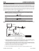
Compressed air flows from an air nozzle in the N7500 Torch Head, travels parallel along the axis of the electrode,
and is directed into the molten puddle. The air solenoid included in the N7500 Control Box accepts ordinary shop
compressed air. An air regulator (supplied by user) should be mounted on the air line and adjacent to the Control
Box. Use at least 60 psi, but not greater than 100 psi input of compressed air to the regulator. “Table 3-14: Com-
pressed Air Input Requirements” shows recommended pressure and volume inputs:
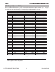
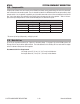
Compressed Air Requirements
Air Pressure Air Volume
psi* kg/cm
2
CFM m
3
/min.
60 4.2 46 1.3
80 5.6 63 1.8
100 7.0 81 2.3
Table 3-14: Compressed Air Input Requirements
*To convert psi to kpa (kilopascals), multiply by 6.895
3.10 Main Air Line
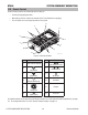
Up to the air regulator mounted (see “Figure 4-9: Assembly Stage 1” on page 4-4) on the N7500 system, the
Primary Air Line may be either rigid or flexible. The inside diameter of the Primary Air Line varies with the length
of the line between compressor and regulator.
Recommended Air Line Requirements
Line length up to 25’ (7.6 m): 1/2” (12.7 mm) inside diameter
Line length above 26’ (7.9 m): 5/8” (15.9 mm) inside diameter