
User Guide
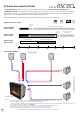

2 Flue Pathway
Using the example building below as a guide, choose the location of the flue terminal* (roof or wall cowl) and establish the
expected flue pathway in your building. The flue pathway will be from the fire to the powerflue terminal, and can be
vertical or horizontal, or a combination of both. This may be through a cavity, a floor, a mid-floor, a roof, to the side of the
fire or any combination of these options.
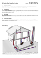
Calculate the total flue length that the flue pipes are likely to follow in your building. Include bends and offsets in your total
length. Allow for some installation tolerance by adding 10% to the total flue run calculation.
3 Flue Length
4 Flue System Selection
With your fire selected, flue terminal located, flue pathway and length established, refer to the accompanying Flue
Selection Guide (DS, DF, DL or DX Series) to determine the flue system options to achieve the complete flue run from fire to
the flue terminal. This may require multiple flue kits.
* The installation and final location of the flue terminal must comply with the relevant Escea Installation Instructions and AS/NZS5601 Gas
Installations. These provide guidance for clearances from the flue terminal to other elements of the building. Non-compliance to these
clearances may decrease performance of the fire or flue, and/or pose a safety risk to the building users.
Example Building
Select the Escea D-Series Gas Fire that meets your design and space requirements. Contact the Escea Architectural
Advisory Team for assistance with any fireplace or flue specification - aa@escea.com
1 Fireplace Selection
DF Series Flue Selection Guide