
Installation manual


ESI Communications Servers Hardware Installation Manual ESI-1000, ESI-600, ESI-200
F.2
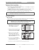
Expansion Cabinet installation
To expand the system, you must add the Expansion Cabinet.
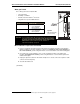
1. Use the expansion cable (supplied with the Expansion Cabinet) to connect the Input jack of the Expansion
Cabinet to the Expansion jack of the Base Cabinet.
2. ESI-1000 and ESI-600 only: Add additional Expansion Cabinets by using the expansion cable to connect
the Input jack of the next Expansion Cabinet to the Expansion jack of the previous cabinet.
3. Connect the ground of all units to the system ground. (See also “Grounding instructions,” page I.1)
4. Connect both power supplies to the standard power strip and then connect to the UPS.
Important: Always apply power to all cabinets simultaneously by using the power strip’s switch.
Do not apply power until all hardware connections have been made.
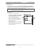
Port card installation
“CS” port cards
“CS” port cards should be inserted from left to right, without skipping any slots. (If there are any empty slots
between port cards, any cards to the right of the empty slot won’t be operational.)
Important: Although all “CS” cards are hot-swappable
1
, ALWAYS power down the entire system (ALL cabinets)
BEFORE adding a new port card or permanently removing an existing port card. Also, be sure to
observe all proper procedures regarding the prevention of electrostatic discharge (ESD) when
performing the following procedures; otherwise, circuit boards may suffer damage.
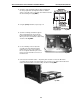
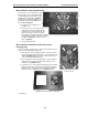
1. On the desired slot in the cabinet, press the
release buttons on the top and bottom to
release the blank faceplate (Fig. 1).
2. Slide the port card into the card guides at the
top and bottom of the cabinet. Then, gently
push the port card into the cabinet (Fig. 2).
3. When you feel some resistance, apply a
little more pressure until you feel the
port card’s edge connectors “click” into the
connector on the backplane. At this point,
the port card’s faceplate should be in contact
with the front of the cabinet.
4. Press the port card’s ejector handles into
the locking position (Fig. 2), so that they click
into place behind the release buttons.
5. If you have no more cards to install at this time, power-up and program the system.
1
If using an “E2” port card in the ESI-200, ESI-600, or ESI-1000, you must also use a Hot-Swap Adapter (ESI part #5000-0462) for hot-swap operations.
Fig. 1
Fig. 2