
Installation manual


ESI Communications Servers Hardware Installation Manual ESI-1000, ESI-600, ESI-200
F.6
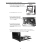
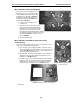
3. Screw two of the standoffs through the drive mounting plate
into the top-right and bottom-right threaded holes with the
spacers. Screw two of the screws that came with the hard drive
into the remaining holes (Fig. MM-3).
4. Using the primary hard drive, repeat steps 1–2.
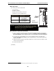
5. Screw the remaining standoffs through the
drive mounting plate into the top-left and
bottom-left threaded holes with the spacers.
When you’re done, the hard drive subassembly
should look like Fig. MM-4.
6. Use the remaining screws to attach the
assembly to the main board through the
main board’s four holes to the standoffs.
Be sure to align the hard drive pins so that
they’re next to the hard drive connectors on
the main board.
7. Connect the two hard drive cables — the primary drive should be connected to J6 and the
secondary drive should be connected to J7. Be sure to tuck the excess ribbon cable between the
main board and hard drives. The full assembly should look like Fig. MM-5.
Fig. MM-3
Fig. MM-4
Fig. MM-5