
Installation manual


ESI Communications Servers Hardware Installation Manual ESI-1000, ESI-600, ESI-200
F.7
Procedure for a hard-drive Memory Module (ESI-600 • ESI-200)
1. Install onto the new Memory Module the standoffs provided with it.
Important: Be careful not to over-tighten the standoffs.
2. Position the Memory Module over the four screwholes and
install the four screws provided with the Memory Module.
Important: Be careful not to over-tighten the screws
into the Memory Module standoffs.
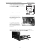
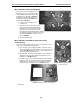
3. Connect the cable provided with the Memory Module to either
J5 (ESI-200) or J6 (ESI-600) on the main board (Fig. MM-6).
Verify that the cable is fully seated at both ends.
Fold excess cable back over the top of the
Memory Module.
Procedure for a CompactFlash Memory Module (ESI-200 only)
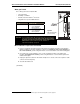
1. Attach the two standoffs to the main board by using
two of the four provided screws. Locate the two holes
closest to J5 on the main board (Fig. MM-7); then,
place the two screws through the holes from the bottom
and loosely attach the standoffs to the screws.
2. Use the two remaining screws to install the
CompactFlash adapter onto the two standoffs.
Important: Be careful not to over-tighten the standoffs.
3. Connect the cable provided with the CompactFlash
Memory Module to J5 on the main board (Fig. MM-7).
Verify that the cable is fully seated at both ends.
Fold excess cable back into the open space between
the main board and the CompactFlash adapter.
4. Slide the CompactFlash Memory Module into the adapter.
Finally, reinstall the main board in the system . . .
1. Slide the main board into the card guides at the top and bottom of the cabinet, and push the main
board gently into the cabinet.
2. When you feel some resistance, apply a little more pressure until you feel the main board “click”
into the connector on the backplane. At this point, the faceplate should be in contact with the front of
the cabinet.
3. Push the ejector handles into their locking position, so that they click into place behind the release buttons.
4. Reconnect to the faceplate’s front panel the cables you removed in step 1 under “First, remove the
main board from the system . . .” (page F.5).
5. Power-up the system.
Important: Remember that, if you have multiple cabinets in the system, you must power-up all of them at
the same time.
Fig. MM-6
Fig. MM-7