
Installation manual


ESI Communications Servers Hardware Installation Manual ESI-1000, ESI-600, ESI-200
F.10
What you’ll need
Here’s what you’ll need to install the M3:
• -inch nut driver.
• #1 Phillips screwdriver.
• A well-lit, clean and static-free
1
work area.
. . . along with these specific additional items:
ESI Communications
Server
Additional items required for
installing the M3
ESI-600
• ESI-600 main board
• A second ESI-600
Memory Module
ESI-200
• ESI-200 main board
• A second ESI-200
Memory Module
Important: To successfully install the M3, you must follow, in the correct order, the
steps listed beginning below. If the main board is already installed in
the system, you’ll need to power down the system and remove the
main board as explained in “Memory Module installation or
replacement” (beginning on page F.5).
M3 installation: Prepare the main board
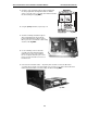
1. If there is a hard drive already mounted on the main board, follow the instructions in the Memory
Module installation instructions (beginning on page F.5). Set aside the four screws and three of
the -inch standoffs; you’ll be using them later to secure the hard drive to the M3 mounting plate.
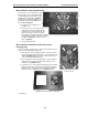
2. Unscrew the two screws holding the cover over the rectangular opening on the main board
faceplate. Set aside the two screws; you’ll be using them later to secure the M3 faceplate to the
main board faceplate.
3. Unplug the expansion cable from the main board (there is no need to remove the expansion cable
connector from the faceplate).
4. Set aside the main board.
(Continued)
1
ESI strongly recommends that an approved ESD wrist strap be worn when working with electronic equipment.
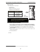
Fig. M3-4:
Main board template
(ESI-600 shown)