
Installation manual


ESI Communications Servers Hardware Installation Manual ESI-1000, ESI-600, ESI-200
F.11
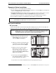
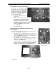
Fig. M3-5: Mount standoffs to M3 board
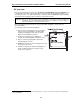
Fig. M3-6: Place nylon spacers
on HDD screw-holes
M3 installation: Prepare the M3 board
There are two sets of mounting holes on the
M3 board. One set is for mounting the M3
on the ESI-200 main board (referenced by
the gray arrows marked “X” in Fig. M3-5);
and the other set aligns with the holes on
the ESI-600 main board (the white arrows
marked “ES” in Fig. M3-5).
1. Locate the four mounting holes on
the M3 board.
2. Using four of the screws and four of the
nylon washers that came with the M3 kit,
install the four 1-inch standoffs onto the
M3 board. The nylon washers should be
placed between the M3 board and the standoffs.
The standoffs should be mounted on the side of
the M3 board without the cable connectors.
Refer to Fig. M3-5.
3. Set aside the M3 board.
M3 installation: Assemble the hard drives to the
mounting plate
For this assembly, you’ll be using six of the -inch standoffs, and one
of the screws, included with the hard drives.
1. Place the mirrored (secondary) hard drive on the work surface
with the printed circuit board up and the connector facing you (as
shown in Fig. M3-6, right). Place a nylon spacer (washer) over
each of the threaded mounting holes.
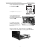
2. Place the right side of drive mounting plate over the hard drive,
aligning the holes in the plate with the threaded holes on the
hard drive (see Fig. M3-7, below).
3. Screw three of the -inch standoffs through the drive mounting
plate into the top-left, top-right, and bottom-right threaded holes
with the spacers. Screw one of the screws that came with the
hard drive into the remaining hole (see Fig. M3-7, below).
Fig. M3-7: Attach the hard drive mounting plate
(Continued)