
Installation manual


ESI Communications Servers Hardware Installation Manual ESI-1000, ESI-600, ESI-200
F.12
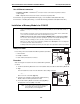
4. Using the primary hard drive, repeat steps 1 and 2 (under “Assemble the hard drives to the
mounting plate,” page F.11).
5. Screw the remaining -inch standoffs through the drive mounting plate into the top-left, top-right,
and bottom-left-threaded holes with the spacers. When done, the hard drive subassembly should
look like Fig. M3-8, below.
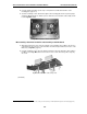
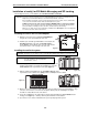
Fig. M3-8: Completed hard drive subassembly
M3 assembly: Attach the hard drive subassembly to the M3 board
1. Align the threaded holes at the end of the standoffs of the hard drive subassembly to the six holes
on the M3 board. The connectors on the hard drives should be facing towards the connectors on the
M3 board (see Fig. M3-3, page F.9).
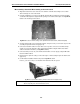
2. Using the remaining screws
1
that came with the hard drives, attach the hard drive subassembly to
the M3 board. See Fig. M-9, below, for the locations of the screws. Note that you’ll be using only
six screws.
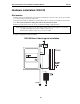
Fig. M3-9: Mount hard drive subassembly on M3
(Continued)
1
If you’re using a drive that was already installed, use the screws you removed in step 1 of “M3 installation: Prepare the main board” (page F.10).