
Installation manual


ESI Communications Servers Hardware Installation Manual ESI-1000, ESI-600, ESI-200
F.13
M3 assembly: Attach the M3 assembly to the main board
1. Align the threaded holes at the end of the four standoffs of the M3 subassembly to the four hard
drive mounting holes on the main board.
2. Using the remaining four screws from the M3 kit, attach the M3 assembly to the main board. Make
sure that the M3 faceplate is aligned with the opening on the main board faceplate. See Fig. M3-10,
below, for the mounting screw locations.
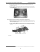
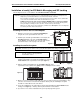
Fig. M3-10: Location of M3 mounting screws (ESI-600 main board shown, without faceplate)
3. Screw the M3 faceplate to the main board faceplate, using the screws you removed in step 2 of “M3
assembly: Prepare the main board” (page F.10).
4. Connect the hard drive cables from each drive to the respective connectors on the M3 board (J5
and J6). To prevent the hard drive cables from interfering with inserting the main board, fold the
cables in toward the hard drives (see Fig. M3-11, below).
5. Connect the M3 (connector J4) to the main board hard drive connector (J6) by using the IDE cable
that came with the M3 kit.
6. Plug back in the expansion cable you removed in step 2 of “M3 assembly: Prepare the main board”
(page F.10).
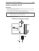
7. Confirm that the installation matches the picture in Fig. M3-11, below.
If it does, you’re done, and you can install the main board back into the system.
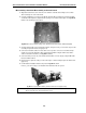
Fig. M3-11: Completed M3 installation (ESI-600 main board and faceplate shown)
Note: The photo in Fig. M3-11 is intended only as a representation. Your M3 installation will look somewhat
different, depending on the ESI Communications Server.