
Installation manual


ESI Communications Servers Hardware Installation Manual ESI-1000, ESI-600, ESI-200
F.16
ESI Presence Management installation
For information on installing ESI Presence Management, see its Installation Manual (ESI # 0450-0792).
ESI Cellular Management installation
Hardware
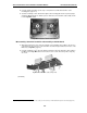
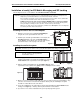
The ESI Cellular Management Access Device (see graphic, below) is housed in a small, ergonomic plastic case,
which connects to a digital phone port. Although the Access Device is intended for desktop placement near
the host ESI phone, it can be attached to any surface by using the included Velcro
®
strips.
The ESI Cellular Management Access Device is powered by the digital port. Each ESI Cellular Management
Access Device requires a single digital port. Only the number of available station ports limits the number of
ESI Cellular Management devices that can be connected to the system.
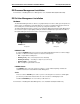
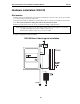
HANDSET LED
Front panel.
PAIRING
button
PC
jack
NETWORK
jack
DIGITAL
jack
Back panel.
HANDSET LED
A single blue HANDSET LED on the front panel of the ESI Cellular Management Access Device displays
the status of a Bluetooth-enabled cell phone as related to the ESI phone:
• Off — Unpaired with a cellular phone.
• Blinking slowly — Not connected (Auto-Connect disabled).
• Blinking moderately — Searching for cell phone (not connected).
• Blinking rapidly — In pairing mode.
• On — Cell phone is paired and connected.
PAIRING button
The PAIRING button, on the rear of the Access Device, is used to initiate the pairing of a Bluetooth-
enabled handset and/or headset with ESI Cellular Management.
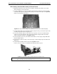
Jacks
The Access Device’s DIGITAL jack is an RJ-11 jack for connecting the Access Device to an ESI digital
port. Power is provided via the included 12-ft. line cord connection to an ESI digital port card.
The PC and NETWORK jacks are reserved for possible future use.
For information on installing ESI Cellular Management, see its Installation Guide (ESI # 0450-1155).