
Installation manual


ESI Communications Servers Hardware Installation Manual ESI-1000, ESI-600, ESI-200
F.17
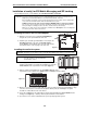
Installation of card(s) for ESI Mobile Messaging and SIP trunking
The following instructions cover installation of the CS-SIP24, CS-SIP8, and CS-ASC.
Important: Each card is for ESI Communications Servers only (except ESI-50L) and requires a Hot-Swap Port Card
Adapter (five-pack, ESI # 5000-0462) if used on an ESI-1000, ESI-600, or ESI-200.
Before installing, verify that the system is running the appropriate system software. If it isn’t, download the
correct version from the ESI Resellers’ Web site and install it on the system.
ALWAYS power-down the entire system (all Cabinets) BEFORE adding or replacing any hardware.
Also, be sure to observe all proper procedures regarding the prevention of electrostatic discharge (ESD)
when performing the following procedures; otherwise, circuit boards may suffer damage.
Whenever you change the port card configuration, you must create a backup file for the new configuration
to be able to perform the Restore function later.
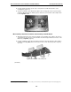
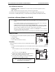
Installing the card on the Port Card Adapter
1. Attach the new card to the assembled Port Card Adapter,
using the five screws provided with the new card.
2. Install the port card cable (provided with the new card) into the
shrouded connector on the new card. Fold the cable as
shown (Fig. C-1), and install the other end of the cable into the
shrouded connector on the top edge of the new card.
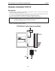
Installing the card in the system
Important: Remember to power down the entire system (all cabinets) before either adding or removing port cards.
Note: Although Figs. C-2 and C-4 show only an ESI-600, the
procedure is similar for other applicable ESI
Communications Servers.
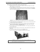
1. On the appropriate cabinet, remove the blank plate covering the slot
in which you’ll install the new card/Port Card Adapter, by using the
release buttons at the top and bottom of the plate (Fig. C-2).
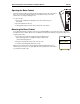
2. Slide the card/Port Card Adapter into the card guides (Fig. C-3) at the
top and bottom of the cabinet. Then, gently push the card/Adapter into the cabinet.
3. When you feel some resistance, apply a little more pressure until you feel the Port Card Adapter’s edge
connectors “click” into the connector on the backplane. At this point, the card/Adapter’s faceplate
should be in contact with the front of the cabinet.
4. Secure the card/Adapter to the cabinet by pressing the Port Card Adapter’s ejector handles into the
locking positon (Fig. C-4), so that they click into place behind the release buttons.
5. If you have no more cards to install at this time, power-up and program the system.
Figure C-1
Figure C-4
Figure C-3
Figure C-2