
Installation manual


ESI Communications Servers Hardware Installation Manual ESI-1000, ESI-600, ESI-200
F.18
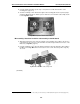
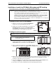
Use of Ethernet connectors
• CS-SIP24 or CS-SIP8 — Both Ethernet
®
connectors must be connected to the private local area
network (LAN).
• ASC — Only Ethernet Connector #1 must be connected to the private LAN.
For information on programming ESI Mobile Messaging, see its Installation Guide (ESI # 0450-1231).
For information on installing SIP trunking, see the ESI SIP Trunking Installation Guide (ESI # 0450-1227).
Installation of Memory Module for CS-ASC
Important: The CS-ASC (Applications Services Card) is for ESI Communications Servers only (except ESI-50L) and
requires a Hot-Swap Port Card Adapter (five-pack, ESI # 5000-0462) if used on an ESI-1000, ESI-600, or
ESI-200.
Before installing, verify that the system is running the appropriate system software. If it isn’t, download the
correct version from the ESI Resellers’ Web site and install it on the system.
ALWAYS power-down the entire system (all Cabinets) BEFORE adding or replacing any hardware.
Also, be sure to observe all proper procedures regarding the prevention of electrostatic discharge (ESD)
when performing the following procedures; otherwise, circuit boards may suffer damage.
Whenever you change the port card configuration, you must create a backup file for the new configuration
to be able to perform the Restore function later.
Installing the ASC Memory Module (hard drive) does not replace the CompactFlash
®
(which is preinstalled).
What you’ll need
Here’s what you’ll need to install the ASC Memory Module (hard drive):
• -inch nut driver
• #1 Phillips screwdriver
• A clean, well-lit, and static-free work area
Procedure
After removing the new card from the box, install the Memory Module
as follows:
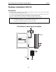
1. Screw into the Memory Module the four -inch standoffs that came with the ASC Memory Module kit.
2. Align:
a. the threaded holes at the end of the hard drive subassembly’s standoffs
. . . to . . .
b. the four holes on the ASC (Fig. H-1).
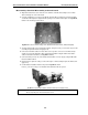
3. Using the four remaining screws that came with the Memory
Module, attach the Memory Module to the ASC.
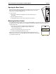
4. Connect the Memory Module’s hard drive cable (Fig. H-2) to
the appropriate connector (U12) on the ASC.
Note: To prevent the cable from interfering with insertion
of the main board, fold the cable in toward the
Memory Module as shown in Fig. H-2.
Figure H-1
Figure H-2