
Installation manual


ESI Communications Servers Hardware Installation Manual ESI-100
G.2
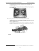
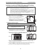
Opening the Base Cabinet
The lid on the Base Cabinet is held in place by two tabs that rest in slots in the bottom
of the case, and a release tab that snaps into an opening in the top-center of the
cabinet and is secured by a retaining screw.
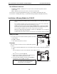
To remove the lid:
1. Remove the retaining screw and depress the release tab at the top of
the cabinet.
2. Rock the lid back from the top.
3. Lift and pull the lid free from the slots in the bottom of the cabinet.
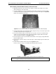
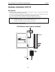
Mounting the Base Cabinet
To mount the ESI-100 Base Cabinet, use the three provided #8 Phillips screws. Note the position of the three
mounting holes in the cabinet. Allow room for installation of the Expansion Cabinet (see page G.3) either now or,
if required, in the future.
1. Screw in the top screw to the backboard (at least half-inch thick
plywood) leaving about one-eighth-inch clearance between the
screw head and the plywood.
2. Hang the unit using the keyhole at the top of the case.
3. Level the unit and install the bottom two screws.
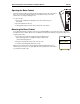
Attach the power transformer to the wall, allowing sufficient length in both cords to
reach the power connector on the upper right side of the cabinet and to reach a UPS
or a dedicated 110 VAC outlet.
Base Cabinet