
Installation manual


ESI Communications Servers Hardware Installation Manual ESI-100
G.3
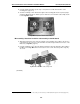
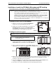
Expansion Cabinet installation
The Expansion Cabinet allows the ESI-100’s capacity to grow by up to two additional port cards. The cards are
connected via ribbon cables, through the opening in the back of the Expansion Cabinet, to the Base Cabinet.
Note: You can add only one Expansion Cabinet to an ESI-100.
To install an Expansion Cabinet:
1. Wear a grounding strap and avoid unnecessary movement while
handling the circuit boards.
2. Unplug the power to the ESI-100 system.
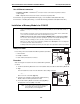
3. Remove the Base Cabinet lid by pressing the release tab at the top of the
cabinet and rock back the lid from the bottom of the cabinet.
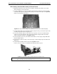
4. Install the Expansion Cabinet on the front of the Base Cabinet in place of
the Base Cabinet's lid.
5. Lock the Expansion Cabinet to the Base Cabinet by snapping the top in
place and reinstalling the retaining screw.
6. Connect the grounding strap from the Expansion Cabinet's grounding lug
(located on the bottom of the cabinet) to the Base Cabinet's grounding
lug. (See also “Grounding instructions,” page I.1).
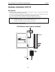
7. Through the large opening in the back of the Expansion Cabinet,
connect the ribbon cable(s) from the port card(s) to the card
directly below.
8. Re-install the original lid from the Base Cabinet on the face of the
Expansion Cabinet.
Port card installation
Adding or replacing port cards will require the system to be taken out of service
(the ESI-100 doesn’t support “hot-swapping” of its port cards).
Notes: The ESI-100 can use only E2 port cards (see “Port card options,” beginning on page A.4).
ALWAYS power down the system BEFORE adding or replacing any hardware. Also, be sure to
observe all proper procedures regarding the prevention of electrostatic discharge (ESD) when performing the
following procedures; otherwise, circuit boards may suffer damage.
Whenever you change the port card configuration, you must create a backup file for the new configuration
to be able to perform the Restore function later.
After removing the E2 port card from the box, install it as follows:
1. Unplug the power supply to the system.
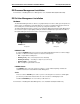
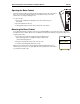
2. Remove the locking screw (at the top of the cabinet, securing
the cover), and then remove the top cover by pressing down
the locking tab and pulling the top cover forward (Fig. PC-1).
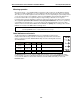
Note: Port cards are added to an existing Base Cabinet in a “piggyback”
fashion — i.e., port card 2 (J1) plugs into port card 1 (J2), port card 3
(J1) plugs into port card 2 (J2), etc.
(Continued)
Fig. PC-1