
Installation manual


ESI Communications Servers Hardware Installation Manual External connections
I.7
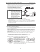
Station connection
Except on the 482 card (ESI-50 only
1
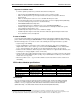
), the first 12 pairs on each Amphenol are station ports:
Port card Digital stations Analog ports ESI Communications Servers supporting
612 12 ESI-1000, ESI-600, ESI-200, ESI-100
D12 12 ESI-1000, ESI-600, ESI-200, ESI-100
DLC12 12 ESI-1000, ESI-600, ESI-200, ESI-100
684 8 4 ESI-1000, ESI-600, ESI-200, ESI-100
A12 12 ESI-1000, ESI-600, ESI-200, ESI-100
A4 4 ESI-1000, ESI-600, ESI-200, ESI-100
482 8 4 ESI-50
1
DLC82 8 2 ESI-50
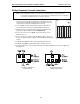
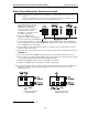
All stations are connected using a single pair. Each port position is pre-numbered and fixed as indicated in the
66 block wiring diagram shown for each port card type.
Note: The station runs can be up to 1,000 ft.
Digital stations
Digital stations for the ESI Communications Server include:
• ESI desktop phones
• ESI Digital Cordless Handset
(II and original)
• ESI Presence Management RFID Readers
2
• ESI Cellular Management Access Devices
3
The digital station wiring is not polarity-sensitive. Only one phone can be connected per digital port.
The station line voltage is 33 VDC.
For proper operation, the combined length of
feed cables, backbone cabling, cross-connect,
and station cable must not exceed 1000 feet
(304 meters) for digital stations. Station line cord
length should not exceed 12 feet (note that this is
the length of the line cord provided with
each ESI desktop phone).
Each digital station can have no more than two
cross-connects or splices in the cable distribution.
Cable construction, termination blocks, and
modular jacks must meet at minimum Category 3
cabling requirements. Additional splices or
terminations will further reduce the maximum
cable length at which the digital station will operate reliably.
Because of potential interference caused by electrical noise, ESI strongly
recommends against distribution of digital stations with analog stations, T1 circuits, PRI circuits, or other
circuits in the same cable binder or station run.
Analog ports
The analog ports do not require that tip-and-ring polarity be observed. The analog ports can be used for
2500-type sets or for devices such as fax machines, modems, etc., that can be connected via a normal
tip-and-ring pair. Each analog port will support only a single analog device. (For total analog port capacity on
each ESI Communications Server, see “System capacities,” page D.1.)
All analog ports provide Type I Caller ID information (Caller ID with call waiting is not supported).
1
The 482 card is supported also by the ESI-50L, the ESI C-Plus, and IVX S-Class (Generation I–II) systems.
2
For information on installing ESI Presence Management, see its Installation Manual (ESI # 0450-0792).
3
For information on installing ESI Cellular Management, see its Installation Guide (ESI # 0450-1155).