
Installation manual


Hardware overview/installation IVX C-Class with voice mail: Installation Manual
B.10
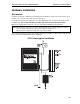
Amphenol cable connections
Connect a standard 66 Block using a male 50-pin Amphenol cable to the port card’s female connector
located on the bottom-right side of the cabinet. The connector closest to the wall is the first port card
(which is the main board on the C-Class).
CO line connection
Local loop
The IVX C-Class system's advanced CO line circuitry provides for open loop detection and the system’s
built-in Caller ID interface.
Note: Observe correct order of connection to preserve proper rotary hunting of the CO lines.
Station connection
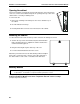
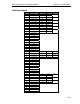
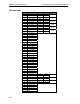
The first six pairs on the Amphenol are station ports.
All stations are connected using a single pair. Each port position is pre-numbered and fixed as indicated
in the 66 block wiring diagram (“Worksheet,” page B.13).
Note: The station runs can be up to 1,000 ft.
Digital stations
The digital station wiring is not polarity-sensitive. Only one phone can be connected per digital port.
Analog ports
The analog ports do not require that tip-and-ring polarity be observed. The analog ports can be used for
2500 type sets or for devices such as fax machines, cordless phones, etc., that can be connected via a
normal tip-and-ring pair. Each analog port will support only a single analog device.
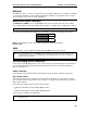
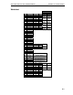
Station Numbering Plan
Digital stations Analog stations
Main board 100 through 105 112 through 113
Port card 1 108 through 112 n/a
Refer to pages B.11 through B.13 for punchdown assignments.