ESI VLS-2000 Video Line Scaler Operating ManualVersion 1.2 ESI VLS-2000 Video Line Scaler Operating Manual Version 1.
ESI VLS-2000 Video Line Scaler Operating ManualVersion 1.2 TABLE OF CONTENTS 1. INTRODUCTION.....................................................................................................................................4 2. INSTALLATION AND SETUP ................................................................................................................5 2.1 .Connections ............................................................................................................................
ESI VLS-2000 Video Line Scaler Operating ManualVersion 1.2 3.2.9 Motion .................................................................................................................................... 11 3.2.10 Black................................................................................................................................... 11 3.2.11 Source ................................................................................................................................. 12 3.2.
ESI VLS-2000 Video Line Scaler Operating ManualVersion 1.2 1. INTRODUCTION The ESI VLS-2000 extends the capabilities of high definition projectors, monitors, and other highresolution display devices. It provides the ability to view a wide range of video sources at the full capabilities of the display.
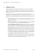
ESI VLS-2000 Video Line Scaler Operating ManualVersion 1.2 2. INSTALLATION AND SETUP 2.1 Connections Figure 2 shows the rear panel layout of the VLS-2000. Input connections are grouped on the left side of the panel. The Output connector is to the right of the Inputs, and the Power connection is at the far right. Figure 2 : VLS-2000 Rear Panel Layout 2.1.1 SVideo Input Connect an S-Video source to this input, using a standard S-Video cable.
ESI VLS-2000 Video Line Scaler Operating ManualVersion 1.2 2.1.5 RGB/YPrPb Output Connect this to the Display System. This could be a Projector, High Definition TV, or Monitor. The VLS-2000 may be configured to connect to RGB or YPrPb Display Systems, with any sync requirement (HV, Sync-On-Y, Sync-On-Green, Tri-Level, or Composite). For connection to equipment with Phono or BNC connectors, breakout cables are available. Consult your dealer. 2.1.
ESI VLS-2000 Video Line Scaler Operating ManualVersion 1.2 have a 4 wire system, with only one composite sync wire, the Composit setting may be required.
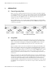
ESI VLS-2000 Video Line Scaler Operating ManualVersion 1.2 3. OPERATION 3.1 Normal Operating Mode Figure 3 shows the overall menu structure. In Normal Operating Mode (Top 4 blocks in Figure 3.1), the buttons allow the choice of any one of the four inputs connected to the VLS-2000. When the VLS-2000 is powered up, it automatically selects the input which was selected when the unit was last powered off. Press SELECT or UP to view a different input.
ESI VLS-2000 Video Line Scaler Operating ManualVersion 1.
ESI VLS-2000 Video Line Scaler Operating ManualVersion 1.2 Figure 3.2 – Setup Menu Structure 3.2.1 Input This chooses the VLS-2000 input to display on the display device. The Video setting displays the device connected to the connector labeled “Video”. The S-Video setting displays the device connected to the connector labeled “S-Video”. The YCrCb setting displays the device connected to the connectors labeled “Y”, “Pr”, and “Pb”. The HDTV setting connects the display device to the HDTV connector.
ESI VLS-2000 Video Line Scaler Operating ManualVersion 1.2 3.2.7 Detail This setting sets up the level of fine image-detail processing the VLS-2000 performs, on a scale of 0 to 10. The nominal setting is 5, but edges can be sharpened with higher numbers, or softened with lower numbers. 3.2.8 Noise This setting controls the amount of noise filtering performed by the VLS-2000, on a scale of 0 to 10. The 5 setting provides nominal filtering.
ESI VLS-2000 Video Line Scaler Operating ManualVersion 1.2 3.2.11 Source This tells the VLS-2000 what type of video source material is being presented to the device input. Combined with the Screen setup, the VLS automatically calculates the best image transformations to perform to get the largest possible image in the correct aspect ration on the display. Source should be set to either 16:9, 4:3Full, or 4:3LtrBx, depending on the format of the supplied input.
ESI VLS-2000 Video Line Scaler Operating ManualVersion 1.2 Output Screen Input Source 16:9 Screen 4:3 Screen No scaling performed. Image is displayed without change. 16:9 image is Vertically scaled down to fit in 4:3 format, centered vertically on the screen, with black areas added top and bottom. 4:3 image is Horizontally scaled down to fit in 4:3 format, centered on the screen, with black areas added right and left. No scaling performed. Image is displayed without change.
ESI VLS-2000 Video Line Scaler Operating ManualVersion 1.2 3.2.12 Save This allows saving a group of control settings for Brightness, Contrast, Color, Tint, Detail, Noise, Motion, Black, and Source. As an example, Input 1 might be connected to cable TV. For movies, the settings might be slightly different than those used for sports events. In that case the settings for movies would be stored in Preset1, and the settings for sports events stored in Preset2.
ESI VLS-2000 Video Line Scaler Operating ManualVersion 1.2 4. TECHNICAL SPECIFICATIONS 4.1 Video Inputs Composite 1 V pp S-Video Y – 700 mv pp C – 286 mv pp Component (YCrCb) Y – 1 V pp Cr – 700 mv pp Cb – 700 mv pp HDTV D15F (Progressive) Note: All inputs are NTSC or PAL interlaced video except HDTV 4.2 Video Outputs 15 Pin female DB15 connector (VGA style). Progressive scan, 59.94 hz frame rate (50 hz PAL). Settable line rate for all major computer or TV standards 4.
ESI VLS-2000 Video Line Scaler Operating ManualVersion 1.2 Low noise YCrCb input stage. 4.5 Video Processing Stage Automatic Film (3:2 pull-down) detection and reconstruction processing. Automatic Video detection and adaptive motion processing. Automatic Still Video / Computer graphics detection and enhancement. Format conversion for all combinations of input and output aspect ratios. Scaling and re-timing to all common display resolutions. 4.6 Output Stage High quality 10-bit DAC.