
Specifications


ESI VLS-2000 Video Line Scaler Operating ManualVersion 1.2
ESI VLS-2000 Video Line Scaler Operating Manual Page 5
2. INSTALLATION AND SETUP
2.1 Connections
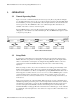
Figure 2 shows the rear panel layout of the VLS-2000. Input connections are grouped on the left
side of the panel. The Output connector is to the right of the Inputs, and the Power connection is
at the far right.
Figure 2 : VLS-2000 Rear Panel Layout
2.1.1 SVideo Input
Connect an S-Video source to this input, using a standard S-Video cable. If the source
equipment has both S-Video and Video connectors, S-Video is preferable to maintain
the highest possible video quality.
2.1.2 Video Input
Connect a composite video source to this input, using a video quality Phono style
cable. If the source equipment has both S-Video and Video connectors, S-Video is
preferable to maintain the highest possible video quality.
2.1.3 YCrCb Input
Connect a Component Video source to this input, using three video quality Phono
style cables. The video source should be labeled to match these three connectors. Do
not connect RGB video sources to this input. YCrCb provides the highest possible
video quality and should be used whenever the source equipment provides it.
2.1.4 HDTV Input
Connect a direct video source to this input. This signal is a pass-thru when selected,
allowing high definition sources to be switched to the projector input. No processing
is performed on this input, so the format, whether YprPb, or RGB, should match the
requirements of the Display System. This will allow the use of high definition sources
which need no video processing. It also allows multiple VLS-2000 units to be chained
together to expand the number of available sources.