Instruction Book Snow Thrower Model 6400 Read and keep this book for future reference. This book contains important information on , SAFETY, ASSEMBLY OPERATION, AND MAINTENANCE.
NOTE: This unit is equipped with an internal combustion engine and must not be used on or near any unimproved forest-covered, brush-covered or grass-covered land unless the engine’s exhaust system is equipped with a spark arrester meeting applicable local or state laws (if any). If a spark arrester is used, it must be maintained in effective working order by the operator. In the State of California, the above is required by law (Section 4442 of the California Public Resources Code).
1 2 1 5 13 10 14 2 11 2 3 8 6 9 4 12 16 7 1 17 15 7 3 4 1 2 12 18 1 9 5 4 7 10 11 1 3 6 16 1 2 5 6 6 7 5 OM6400 15 3
13 15 13 14 9 10 12 3 4 16 13 17 2 14 18 1 11 16 15 6 3 2 5 8 4 5 3 17 18 2 4 3 “A” OM6400 5
20 19 4 6 5 8 1 8 9 4 21 22 2 3 5 3 4 6 4 24 23 11 3 12 11 2 3 10 OM6400 15 6
25 26 11 13 16 7 16 7 14 17 8 7 19 OM6400 13 20 7 17
27 2- 9524 OM6400 2- 3943 2 - 73826 8 1- Extension cord
ENGLISH CONTENTS PRODUCT INFORMATION OWNER’S INFORMATION INTERNATIONAL PICTORIALS ASSEMBLY OPERATION MAINTENANCE TROUBLE SHOOTING CHART 9 9 10 12 12 15 18 TWO YEAR LIMITED WARRANTY Ardisam, Inc.
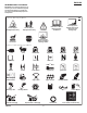
ENGLISH INTERNATIONAL PICTORIALS IMPORTANT: The following pictorials are located on your unit or on literature supplied with the product. Before you operate the unit, learn and understand the purpose for each pictorial. 28 Safety Warning Symbols DANGER Thrown Objects. Keep Bystanders Away. DANGER Thrown Objects. Keep Bystanders Away. WARNING Hot Surface STOP DANGER Avoid Injury From Rotating Auger. Keep Hands, Feet And Clothing Away. IMPORTANT Read Owner’s Manual Before Operating This Machine.
Safe Operation Practices for Snow Throwers As Recommended By: American National Standards Institute. IMPORTANT: Safety standards require operator presence controls to minimize the risk of injury. Your snow thrower is equipped with such controls. Do not attempt to defeat the function of the operator presence control under any circumstances. Training 1. Read the operating and service instruction manual carefully. Be thoroughly familiar with the controls and the proper use of the equipment.
Fuel Switch Shuts OFF/ON flow from tank
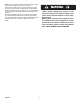
How To Go Forward or Backward (Figure 2) 1. To change the ground speed, first release the traction drive lever (1) and then move the speed shift lever (6) to the desired speed. 2. Ground speed is determined by snow conditions. Select the speed by moving the speed shift lever (6) into the appropriate notch on the shift lever plate. Speed 1, 2 Wet, Heavy Speed 3 Light Speed 4 Very Light Speed 5, 6 Transport only 3. To go forward, engage the traction drive lever (1).
1. With the engine running, quickly pull the recoil starter handle (12) three or four times with a continuous full arm stroke. This will produce a loud clattering sound that is not harmful to the engine or starter. 2. Stop the engine. Wipe all snow and moisture from the carburetor cover, control levers and cables. Also move the throttle control (13), choke control (14), and recoil starter handle (12) several times.
ENGLISH MAINTENANCE CHART CUSTOMER RESPONSIBILITIES SERVICE RECORDS Fill in dates as you complete regular service.
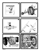
CAUTION: Any greasing or oiling of the above components can cause contamination of the friction wheel (3). If the disc drive plate (1) or the friction wheel (3) become contaminated with grease or oil, damage to the friction wheel will result. 3. The auger gear case is lubricated at the factory and does not require additional lubrication. If for some reason the lubricant leaks out, have the auger gear case checked by a factory authorized service center.
engine pulley
WARNING: For safety and to protect the machine, use only original equipment shear bolts. To replace a broken shear bolt, proceed as follows. Extra shear bolts are provided in the assembly parts bag. 1. (Figure 2) Move the throttle control (13) to the stop position. Disengage all controls. 2. Disconnect the spark plug wire. Make sure all moving parts have stopped. 3. (Figure 9) Lubricate the auger shaft Zerk fitting (1), if equipped, with a grease gun. 4.
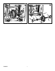
MODEL 6400 REPAIR PARTS ENGINE 16 2 12 17 18 5 20 22 25-2 24 25-1 12 10 13 6 25-3 4 7 23 15 11 8 25-5 25-2 25-4 9 Ref.Drive Page 3 Ref. Auger Housing Page Key No. Part No . Description 2 3 4 5 6 7 8 9 10 11 12 13 14 15 - - - - - 2x97 28x76 710026 1501109 710247 71063 71015 37X136 37X137 1501112 YZ 1501065 71060 910828 ENGINE BOLT, CARRIAGE 5/16-18 RETAINER, PUSH NUT, HEX 5/16-18 PULLEY, ENGINE WASHER WASHER .38ID SCREW, 3/8-24X1.00 BELT, DRIVE V 3L BELT, V 4L 38.
6134 6135 6136 6137
MODEL 6400 REPAIR PARTS FRAME 160 106 105 166 145 162 108 112 111 Ref. Engine Page Ref. Auger Housing Page 166 162 Ref.
MODEL 6400 REPAIR PARTS FRAME Key No. Part No. OM6400 Description 90 1501055E701 COVER, BOTTOM 91 310169 SCREW, 1/4-20X .63 103 1501126 YZ IDLER ASSEMBLY, AUGER 105 711682 PIN, HAIR .38DIAX1.64LG 106 761761 PIN, KLIK 3/16” DIA 107 165X159 SPRING, TENSION 108 761675 YZ ASSY., SPRING ATTACH 110 585781 BOLT, 3/8-16X1.25 CARR. 111 711617 WASHER, FLAT 122 25X020 SCREW, TAP 5/16-18 X .
MODEL 6400 REPAIR PARTS DRIVE 229 Ref. Shift Yoke Page Ref. Frame Page Ref. Wheel Page 200 221 225 223 Ref. Wheel Page 226 206 227 201 229 234 232 236 203 204 204 234 203 230 238 215 218 Ref. Wheel Page 207 215 213 Ref.
MODEL 6400 REPAIR PARTS DRIVE Key No. Part No. OM6400 Description 200 1501092 YZ LF AXLE, SWING PLATE YZ 201 579851 CHAIN, ROLLER #42x19.00 203 334163 BEARING AND RETAINER, ASSY 204 579858 WASHER 206 780055 SCREW, TAP 5/16-18x0.5 207 1501100 ASSY, HEX SHAFT 208 579868 CHAIN, ROLLER #36x18.
MODEL 6400 480 REPAIR PARTS AUGER HOUSING 484 482 499 490 527 500 485 522 523 491 509 526 525 493 511 522 523 520 Ref.
MODEL 6400 REPAIR PARTS AUGER HOUSING Key No. Part No. OM6400 Description 480 1501211 PULLEY 482 2001022 KEY, SQUARE 484 577400 SCREW, 5/16-18 X 0.63 485 1501158 SPACER, FRICTION PULLEY 490 582957 YZ RETAINER, BALL BRNG 491 43846 BEARING, BALL 493 001X92 BOLT, HEX - 0.31-18X0.50 499 710026 NUT, 5/16-18 HEXWDFLLK 500 1501436E245 HOUSING, ASSY 509 760040 PLUG, CHRISTMAS TREE 510 760657E701 BLADE, SCRAPER 511 340720 BOLT, 1/4-20X.
MODEL 6400 REPAIR PARTS HANDLE 766 729 739 731 734 766 730 734 735 739 729 740 733 720 725 721 741 724 728 727 725 726 755 727 726 724 765 750 752 756 751 757 725 743 765 764 763 744 Ref.
MODEL 6400 REPAIR PARTS HANDLE Key No. Part No. OM6400 Description 720 337056E701 HANDLE, UPPER LH 721 337057E701 HANDLE, UPPER RH 724 11234 SCREW, 5/16-18X2.75 725 71071 WASHER, FLAT 726 71060 WASHER, SPTLK .31X.58X.
MODEL 6400 REPAIR PARTS GEAR CASE 340 341 327 326 304 324 323 325 306 322 321 324 312 311 304 303 316 300 310 310 301 312 313 315 320 314 311 303 GEAR104A Key No. Part No.
MODEL 6400 REPAIR PARTS CONTROL PANEL 771 770 772 Key No. Part No.
MODEL 6400 REPAIR PARTS DISCHARGE CHUTE 600 600 596 597 583 584 599 582 600 602 610 603 601 609 609 606 611 607 607 Ref. Auger Housing Page CHUTE100A Key No. Part No. OM6400 Description 582 585280 BOLT, 5/16-18 X 1.00 CARR. 583 71071 WASHER, FLAT 584 71038 NUT, 5/16-18 NYLOCK 596 71071 WASHER 597 1501260 KNOB, WING 3.00 598 71037 NUT, 5/16-18 REGHEX 599 002X97 BOLT, 5/16-18 CARR. YZ 600 762222 CHUTE ASSEMBLY 601 586280 BOLT, 5/16-18 CARR.
MODEL 6400 REPAIR PARTS CHUTE ROD 856 855 854 855 Ref. Handle Assy 863 860 861 870 864 867 864 852-9 852-5 852-8 Ref. Auger Housing Assy 852-13 852-10 852-1 1 852-1 852-2 868 852-6 852-7 Key No. Description Part No. Key No. 852-3 Description 869 CROD105B Part No.
MODEL 6400 REPAIR PARTS WHEELS 679 678 673 675 671 654 650 678 655 652 676 Ref. Drive Page 655 671 673 653 675 677 WHL100A Key No. Part No. OM6400 Description 650 1501283 SHAFT, AXLE 652 1501089 SPRKT & HUB 653 01x193 SCREW, 1/4-20 x 1.75 654 15x145 NUT, 1/4-20 HEX NYLOCK 655 1501114 BEARING, AXLE 671 712120 FLATWASHER 673 1501139 BUSHING, WHEEL 675 318503 TIRE & RIM 676 577015 SCREW, 1/4-20X1.