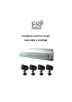
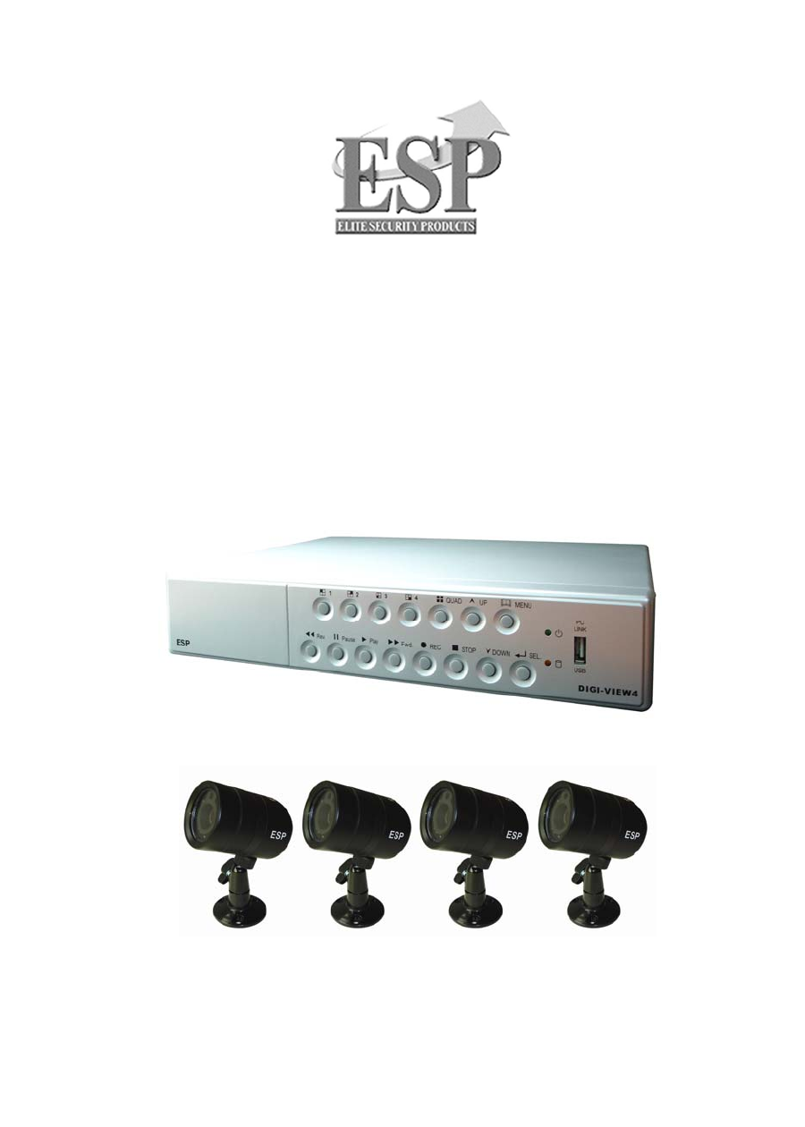
Installation and User Guide DIGI-VIEW 4 SYSTEM
Regulatory FCC Certification This equipment has been tested and found to comply with the limits for a class A digital device, pursuant to Part 15 of the FCC rules. These limits are designed to provide reasonable protection against harmful interference when the equipment is operated in a commercial environment. This equipment generates, uses, and can radiate radio frequency energy and, if not installed and used in accordance with the instruction manual, may cause harmful interference to radio communications.
CONTENTS System Introduction ---------------------------------------------------------------- 1 Package Content --------------------------------------------------------------------2 DVR Front Panel Buttons --------------------------------------------------------- 3 DVR Back Panel Buttons -------------------------------------------------------- 4 Video Output Connection (To TV/Monitor) ----------------------------------- 5 Video Input Connection (Camera) -------------------------------
OSD Operation Guide: Over Write ------------------------------------------------- 18 OSD Operation Guide: HDD Size and HDD used ------------------------------ 18 OSD Operation Guide: HDD Format ---------------------------------------------- 18 OSD Operation Guide: Sensor Setup Menu ------------------------------------- 19 OSD Operation Guide: Motion Setup Menu -------------------------------------- 20 How to backup through USB to PC ------------------------------------------------- 21 Print Ev
SYSTEM INTRODUCTION DIGI-VIEW 4 SYSTEM is a CCTV surveillance system for home and small office uses. Connecting four cameras to DVR (Digital Video Recorder), you can enjoy various functions DVR provides. The Digital Video Recorder (DVR) is for recording / retrieving video streams up to 4 channels at the same time. It adapts a digital image compression technology to compress the input channel video streams, and uses a HDD (Hard Disk Drive) to record the compressed video stream.
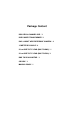
Package Content DIGI-VIEW 4 CHANNEL DVR * 1 DVR POWER TRANSFORMER *1 DAY & NIGHT WEATHERPROOF CAMERA * 4 15 METER DIY CABLE * 4 50 cm DVR TO TV LEAD (BNC TO BNC) * 1 50 cm DVR TO TV LEAD (BNC TO RCA) *1 BNC TO RCA ADAPTOR * 1 CD DSIK * 1 MANUAL BOOK * 1
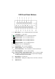
DVR Front Panel Buttons 1. Menu button:Press to display Operation menu option 2. 2. Up button:used in menu 3. All channels button:Press to display all channels 4. Channel 4 button:Press to display channel 4 5. Channel 3 button:Press to display channel 3 6. Channel 2 button:Press to display channel 2 7. Channel 1 button:Press to display channel 1 8. Reverse : Press to rewind playback 9. Pause button:Press to pause playback 10. f Playback button:Press to start playback 11.
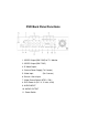
DVR Back Panel Functions 1. VIDEO Output (BNC ONE) to TV / Monitor 2. VIDEO Output (BNC TWO) 3. S-Video Output 4. Camera Power Supply (To Camera) 5. Video Input (For Camera) 6. Sensor / Alarm Input 7. Video Format Switch (NTSC / PAL) 8. DVR Power In (DC- in, 12 volts, 4.0A) 9. AUDIO INPUT 10. AUDIO OUTPUT 11.
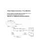
Video Output Connection ( TV or Monitor) Connect a TV (Monitor) to the DVR using one of the video output connectors. The DVR provides 1 x S-Video and 2 x BNC video outputs. The below figure shows the video line connection. WHAT’S BNC => IT’S CONNECTOR FOR YOUR CABLE TV INPUT IN TV. WHAT’S RCA => IT’S CONNECTOR FOR YOUR VCR / PS2 INPUT IN TV.
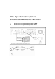
Video Input Connection (Camera) Connect cameras to the DVR. The DVR provides 4 x BNC connectors. The camera installation procedure is shown below: I. II. Connect the video signal line and power to the DVR. Connect the video signal line and power to camera.
Advanced Installation Sensor Installation The DVR has 4 sensor inputs, one for each channel. The sensor Installation Procedure is as the following: I. Connect the sensor signal line to the unit. The sensor signal terminal is on the DVR rear panel. II.Connect the sensor adaptor jack into the sensor, and plug in the power adaptor.
Advanced Installation Alarm Installation The DVR includes one internal switch for sounding an alarm when any of the sensor inputs is activated. The switch is normally open and closed upon activation. The circuitry is shown in the above figure. The alarm is installed as follows: I.The alarm requires a power supply, which is normally supplied with the alarm. II.Connect the alarm power line to the alarm switch terminal on the rear of the DVR.
Switch On the DVR Before turn on the power, please make sure Video Format is in right position NTSC Area : North America, Japan, Philippines, Taiwan & etc. PAL Area : Europe, South America, Australia, Mid-East & Africa Asian Countries most use PAL like Indonesia, Thailand, Malaysia and etc. Once the DVR and HDD have been properly installed (please refer to pages 3 ~ 8 for further details about DVR installation) the unit is ready to record and display. Apply power and switch on.
Record Press z button on the front panel to start record. The DVR will record the selected images and save them onto the HDD. A sample of recording a quad view is shown below: z displayed on the screen indicates the activation of recording. A circular symbol Any specific channel or quad view can be displayed on the monitor by pressing the appropriate Channel Select button while recording is in the process. Press the button to stop video recording.
Play Menu Press f (play button) to open the playback menu as shown below. HARD DRIVE:MASTER 05/06/18 17:26:47-05/06/25 17:28:23 01 TIME 2005/06/18 17:26:47 02 TIME 2005/06/19 17:25:47 03 TIME 2005/06/19 20:03:50 PRESS﹝∧,∨﹞THEN﹝SELECT﹞ PRESS ﹝MENU﹞TO EXIT List of events triggered by installed sensors or motion detection. Available recordings in the HDD can be played. Pressing button to start time and date search mode. Position the cursor using the ▲ and ▼ buttons to select the date and/or time.
MAIN MENU Press the button to display the main menu. CAMERA SELECT 1234 RECORD SELECT 1234 RECORD MODE EACH RECORD FRAMERATE 30 VIDEO QUALITY HIGH RECORD SCHEDULE =SUB MENU= HARD DRIVE SETUP SENSOR SETUP NETWORK SETUP PRESS﹝∧,∨﹞THEN﹝SELECT﹞ PRESS ﹝MENU﹞TO EXIT Use the ▼ and ▲ buttons to move the cursor up and down. Press to enter the selected sub-menu. Use the ▼ and ▲ buttons to position the cursor. Press to cycle through until reaching the desired option.
Operation Guide: RECORD SELECT Used to select the cameras whose video inputs will be recorded on the HDD. Desired cameras must be pre-selected in the “Camera Menu” in order to perform recording properly. Use to cycle through the options. Press to make the selection and return to the main directory. NOTE: Desired channels cannot be recorded properly if the corresponding cameras are not pre-selected in the “Camera Menu.” Operation Guide: RECORD MODE Can be set to either “EACH” or “QUAD”.
Operation Guide: SCHEDULE RECORD MAIN MENU CAMERA SELECT 1234 RECORD SELECT 1234 RECORD MODE 田 RECORD FRAMERATE 30 VIDEO QUALITY HI ¾RECORD SCHEDULE SUB MENU HARD DRIVE SETUP SENSOR SETUP Select this option to change a recording schedule during a day (24-hour period) Numbers below indicate the time duration in 24 hour format. (T) 24-hour recording. (S) Motion recording. The DVR only starts recording when an event (motion or GPIO) is triggered.
Operation Guide: SUB MENU SUB MENU ¾PASSWORD CHANGE TIME SET BUZZER SOUND AUTO RECORD AUDIO RECORD AUDIO OUT MUTE AUDIO CHANNEL [OFF] [OFF] [ON] [OFF] [1] Sub Menu allows users to change system password, system date and time, as well as various audio functions and auto record. Use (¿À) to move cursor and select. Press ( ) to either cycle through the options or enter subsidiary menus.
Operation Guide: TIME SETUP TIME 2004/03/21 03:23:21 ▼ and ▲ -- Position Year, Month, Day, Hour, Minute or Seconds. -- Cycle through options (0,1,2 …9) PRESS (¿À), THEN (SELECT ) PRESS(MENU) TO EXIT -- Exit Operation Guide: BUZZER SETUP BUZZER :ON Use the ▼ and ▲ to select buzzer options Press to choose ON/OFF. Press to return to the main menu. ON: DVR buzzer sounds when video input signal loss is detected. Operation Guide: AUTO RECORD SETUP AUTO RECORD :ON Press to choose ON/OFF.
Operation Guide: AUDIO MUTE AUDIO OUT MUTE :ON Use ▼ and ▲ to select audio out mute. Press to choose ON/OFF. Press to return to the main menu. Operation Guide: AUDIO CHANNEL SELECT AUDIO CHANNEL : 1 Use ▼ and ▲ to select audio channel. Press to cycle through options. (Channel 1,2,3,4) Press to return to the main menu. DVR only records one channel of audio.
Hard Disk Drive Setup Menu OVERWRITE ENABLED MASTER HDD SIZE MASTER HDD USED MASTER HDD FORMAT SLAVE HDD SIZE SLAVE HDD USED SLAVE HDD FORMAT HARD DRIVE SETUP YES 400MB 0MB 0% N/A N/A PRESS (<,>) THEN (SELECT) PRESS (MENU) TO EXIT Operation Guide: OVER WRITE “YES”. The DVR will record continuously and overwrite the recorded data when the HDD is full. “NO”. The unit will stop recording once the HDD is full. Use ▼ and ▲ to select OVERWRITE ENABLED. Press to choose YES/NO. Press to return to the SUB menu.
SENSOR SETUP MENU SENSOR SETUP SENSOR RECORD TIME ALARM ON TIME 15 20 SENSOR SET UP MOTION SETUP PRESS (<,>) THEN (SELECT) PRESS (MENU) TO EXIT SENSOR RECORD TIME: Recording duration once sensor Being triggered. Selects record time from 0 ~180 seconds. ALARM OUT TIME: It controls how long ( in second) the alarm sounds after being triggered. Selects alarm ON time from 0 ~ 30 or continuous.
MOTION SETUP MENU MOTION DETECTION CHANNEL-1 SENSITIV 0 (OFF) AREA SETUP CHANNEL-2 SENSITIV 1 AREA SETUP CHANNEL-3 SENSITIV 5 AREA SETUP CHANNEL-4 SENSITIV 2 AREA SETUP PRESS (<,>) THEN (SELECT) PRESS (MENU) TO EXIT MOTION SET UP SENSITIVITY: Sets the sensitivity level for Motion Detection. 0 (OFF) to 5 (maximum sensitivity). ▼ and ▲ buttons to select the sensitivity for each Channel button to select the level. AREA SETUP: Used to define up to two zones per Channel where motion is to be detected.
How to Backup through USB port to PC Backup through USB port The unit provides one USB port to simple backup over the connection with PC. Please mind the following steps to successful link. Warning: Please don’t press “MENU” button during linking status, it would likely lead to unpredictable Error on your PC. Once the PC Link has been activated the DVR play and record functions will be inoperable as control is passed to the connected PC.
Hints: When PC detects USB storage setup, PC has connected DVR host already. Switch on PC LINK play program for 20~30 seconds, you can see following footage. 1. Fast rewind 2. Play next frame 3. Rewind 4. Pause 5. Play 6. Play previous play 7. Fast forward 8. EVENT Search 9. Channel selection 10. BMP picture file 11. Copy MYS file 12. Copy AVI file 13. MYS player 14. SOUND ON/OFF 15. Video search bar If there is no picture, HDD is not detected. Close the software of USB LINK and disconnect the USB cable.
PRINT EVENT Move the mouse to 8 ( Event search), and select the event you want.Then, click OK to play the event recorded. The menu is shown below. Copy the images and record the images DVR host play program offers dynamic and static image output. You can easily copy the static image, and store it in BMP file, or store a certain part of record in AVI file. The converted images can be played by PC software (such as Media Player). Hints: USB LINK work system supports Win 2000 / XP.
DVR SPECIFICATION Image Compression Video Signal NTSC PAL 720 X 480 720 X 576 120 fps (4 x 30) fps) 100 fps (4 x 25) Each Mode 320 x 112 320 x 136 Quad Mode 640 x 224 (total) 640 x 272 (total) Each Mode 7.5 fps 6.25fps Quad Mode 30 fps 25 fps Image Resolution Display Rate Display Rate Video Record Resolution Advanced M-JPEG Frame Rate Video Recording Mode Display Mode Video Input Audio Input Continuous / Schedule / Alarm / Motion Full Screen / Quad 4 x BNC¸ 1.
CAMERA SPECIFICATION Pick Up Elements SHARP ¼” CCD Image Sensor Number of Pixels 500 H * 582 V Back Light Compensation ON Auto Electronics Shutter ON AGC ON Sync. Mode Internal Sync. Scanning System 2:1 Interlace Auto White Balance ON Resolution 420 TV Lines S/N Ratio More than 48dB Gamma 0.45 Minimum illumination 045 Horizontal Sync. Frequency 28.3KHz Video Output 1.
Technical Support 0121 7861881