* 10/ Hydronic * M (Water Heater) Hydronic Espar Heater Systems Tech n i c a l D e s c r i p t i o n Installation Instructions Operating Instructions Maintenance Instructions Tr o u bl e s h o o t i n g a n d R e p a i r I n s t r u c t i o n s Par t s L i s t Espar Products, Inc. 6099A Vipond Drive Mississauga, Ontario Canada L5T 2B2 (905) 670-0960 (800) 387-4800 Canada & U.S.A. (905) 670-0728 Fax www.espar.
Table of Contents Page Introduction Heater Warnings Introduction Specifications Heater Components Principal Dimensions ........................................................ ........................................................ ........................................................ ........................................................ ........................................................
Introduction Heater Wa r n i n g s Wa r n i n g To I n s t a l l e r • Correct installation of this heater is necessary to ensure safe and proper operation. Read and understand this manual before attempting to install the heater. Failure to follow all these instructions could cause serious or fatal injury. C a u t i o n: During electrical welding work on the vehicle disconnect the power to the heater in order to protect the control unit.
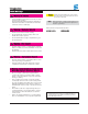
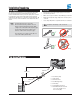
Introduction E s p a r ’s H y d ronic 10 Coolant Heater Quality engineered to provide a dependable means of heating, the Espar Hydronic 10 is a diesel fired coolant heater capable of between 1.5 kW to 9.5 kW/hr (5,100 to 32,400 BTU/hr). The heater can be purchased either in a weather resistant box to protect it from the elements and provide for ease of installation or in the universal form. This light weight and compact coolant heater offers an affordable heating solution to many applications.
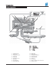
Introduction Heater Components 17 18 16 + we 09:20 P 4 5 – 15 6 3 7 V 9 8 14 B WE 1 2 10 V A 12 1 2 3 4 5 6 7 8 9 13 Combustion motor Flame sensor Combustion chamber Control unit Heater plug Temperature sensor Flame tube Heat exchanger Overheating switch 11 WE WA V B A = = = = = Wa t e r i n l e t Wa t e r o u t l e t C o m bu s t i o n a i r Fuel Fumes 10 11 12 13 14 15 16 17 18 Water pump Exhaust silencer Combustion air silencer Fuel feeder pump Fuel branch piece Cable tree Fu
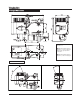
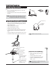
Introduction Principal Dimensions * 10 HYDRONIC Espar Combustion air Exhaust air Water Inlet * All measurements in millimeters 25.4 mm = 1” 20.2 Minimum installation distance (clearance) to open the lid and to dismount the glow pin and the control unit. Minimum installation distance (clearance) to take in heating air.
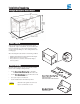
Installation Procedures P r i n c i p a l D i m e n s i o n s - B ox ed Vers i o n Heater Location Always mount the heater in a protected area. Eg: storage compartment, engine compartments, step box or battery box. Espar recommends you use the boxed unit. Boxed heaters can be mounted by utilizing one of the existing brackets. See following page. When mounting the heater adhere to the following conditions: • Situate the heater below the normal coolant level of the engine.
Installation Procedures Heater Plumbing The heater is incorporated into the engine’s cooling system for engine preheating • Take the coolant from a low point on the engine to reduce aeration in the system. • Ensure proper direction of coolant flow by taking coolant from a high pressure point in the engine and returning it to a low pressure point. (ie. pickup from back of block and return to the suction side of the engine's water pump).
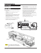
Installation Procedures Fuel Line Fuel System The Hydronic 10 boxed unit is most commonly provided with the fuel metering pump mounted inside the box. This is to reduce installation time and to protect the pump from corrosion. If specifications cannot be met the pump must be mounted externally. See illustration for connections and specifications. All parts necessary to do the installation are included in the kit as shown. Note: • Route fuel lines from the fuel pick-up pipe to the heater.
Installation Procedures Fuel Metering Pump Installation If the pump needs to be mounted externally follow these guidelines: • Choose a protected mounting location close to the fuel pick-up pipe and heater. • Using the bracket and rubber mount provided, install pump as shown. 15° to vertical 15° N o t e : Proper mounting angle of the pump is necessary to allow any air or vapor in the fuel lines to pass through the pump rather than cause a blockage.
Installation Procedures Electrical Connections Caution: To avoid potential short circuit damage during installation, insert 20 amp fuse into the power harness after all electrical connections are complete. A) Po wer Harness................................................................... N o t e : Wire must be inserted into fuse holder prior to terminating. N o t e : All harnesses should be cut to length. All exposed electrical connections should be coated with protective grease.
Installation Procedures Exhaust Connection Intake Connection A 30 mm flexible tube exhaust pipe with a length of 1M long is supplied with the kit for the exhaust. An exhaust clamp is needed to secure the exhaust to the the heater. The exhaust hose cannot be any longer than 2 m. Connect the exhaust as follows: Universal versions only: • Connect the exhaust pipe to the exhaust port on the heater and attach with clamp provided.
Installation Procedures O p e r a t i n g S w i t ch e s A Push/Pull switch, or a 7 Day Timer are available for the heater. Both are discussed on the following pages. Connect the operating switch as follows. Multifunction The 7 Day Timer has been designed to provide a simple means to control the operation of the heater system and to include the capability for diagnostics. This timer connects to the diagnostic circuit of the heater.
Installation Procedures P u s h / P u l l S w i t ch • Mount switch in a location where it is easily accessible • Mount using hardware supplied • Connect the switch harness to the connector at the heater and run the harness to the switch location • Cut harness to length at the switch and install terminals • Connect wiring as described below N o t e : Wired described the switch light glows when pulled out and is off when pushed in.
Installation Procedures 7 uDbatyi t lT sa t rguec t i o n s S ei m R iegrhItnP Changing the Time or Day To Use Preset Start Times Push and hold button until the time display begins to flash. Continue to set the time as listed in setting time and weekday. Press the P button until the desired memory location appears in the display. The heater will start at the day and time displayed. The display will go off in 15 seconds. The memory location number will stay displayed (1, 2 or 3).
Notes 16
Heater Operation P r e - S t a r t P ro c e d u r e s Upon completion of installation prepare the heater as follows: • Check all fuel, electrical and plumbing connections. • Refill the engine coolant. • Bleed air from the coolant system by running the engine and refilling the antifreeze as needed. Resecure heater hose. • Run engine to further bleed the system • Top up engine coolant.
Heater Operation O p e r a t i o n a l F l ow C h a r t RUNNING PHASE STARTING PHASE Operating Mode System Check Pre-heat Ignition Attempt Ignition Attempt Pre-heat 2nd. attempt SHUT DOWN PHASE Controlled Heating After Glow Cool Down Off or Stand by 2nd. attempt Off On On On On On On On Off On: if in stand by Off On On On On On On On Off Off On On On On Off On Off Off Off Off On Off On On Off Off Off 80 sec. Up to 90 sec. 80 sec. 1- 3 sec.
Heater Operation H y d ronic 10 W i r i n g D i agram - 12 Volt + 24 Vo l t 25 2081 05 - 12V 25 2044 05 - 24V Diagnostic LED 2.2 2.7.1 YELLOW h) RED RED BLUE Push/Pull switch RED/YELLOW BLUE/WHITE YELLOW BROWN 2.7 RED GREEN 3.1.1 RED YELLOW 0 0 BROWN 15 (K) 3.2.9 RED GREEN b c d e K (15) 31 5.1 BROWN B1 1 2 3 4 5 6 7 8 9 10 11 12 13 14 Brown RED 2.1 Optional 1 2 3 4 5 6 7 8 9 10 11 12 13 14 15 16 17 Grey Black 18 1.2 1.5 3 14 1.12 1.1 1.2 1.5 1.
Heater Operation H y d ronic 10 W i r i n g D i agram - 12 Volt + 24 Vo l t - U n i v e rs a l H a r n e s s 25 2081 05 - 12V 25 2044 05 - 24V 2.5.7 Diagnostic LED YELLOW h) BLUE RED/GREY RED BROWN/WHITE BLACK/VIOLET c BLACK 2.2 Push/Pull switch 3.2.9 b c d e RED/YELLOW BLUE/WHITE GREEN/GREY 2 0 0 BROWN 15 (K) K (15) 31 2.7.1 RED BROWN RED 2.7 B1 1 YELLOW 2.7.2 ab RED/WHITE GREEN YELLOW BROWN 3.1.1 RED 3 4 5 6 7 8 9 10 11 12 5.
Heater Operation H y d ro n i c M W i r i n g D i agram - 12 Volt and 24 Volt - Engine Heat Only LED 25 2160 05 - 12V 25 2227 05 - 24V 2.2 Diagnostic LED YELLOW h) BROWN BLUE a6) b) RED BROWN BROWN RED 25 2227 05 only l) k) a2) a3) a4) a5) Push/Pull switch D 3.1.1 BROWN YELLOW YELLOW B1 0 0 BROWN 5.1 C 15 (K) K (15) A 2.1 B RED 2.7 2.7.
Heater Operation H y d ro n i c M W i r i n g D i agram - 12 Volt and 24 Volt - Univers a l H a r n e s s 25 2160 05 - 12V 25 2227 05 - 24V 2.5.7 2.5.18 2.2 Diagnostic 5.10 BROWN RED/YELLOW RED BROWN BK/VT BLACK LED YELLOW c) c) h) BLUE a6) b) RED BROWN BROWN RED l) k) a2) a3) a4) a5) 25 2227 05 Only Push/Pull switch YELLOW C 15 (K) RED 2.7.1 2.7.1 Optional 1.13 1.12 1.1 B5 B3 1.1 1.2 1.5 1.12 1.13 2.1 2.12 2.2 2.5.7 2.5.18 2.7 2.7.1 2.7.5 3.2.9 5.1 5.
Maintenance, Troubleshooting & Repairs Pe i c RMi gahi nt tP en S urbi toi tdl e aa gn ec e • Check coolant hoses, clamps, and make sure all valves are open. Maintain the engine manufacturers recommended coolant level and ensure that the heater is properly bled after service on or involving the coolant system. • Visual check of all fuel lines for leaks. Check and if necessary replace fuel filter inserts. • Visual check of electrical lines and connections for corrosion.
Advanced warning - undervoltage Overvoltage shutdown 002 010 Under voltage shut down Overheating Excessive temperature at flame sensor Possible overheating detected 011 012 013 014 charging system. Advanced warning - overvoltage 001 Fa u l t D e s c r i p t i o n Normal Operation Fa u l t C o d e 000 10 kohms at +25°C. temperature sensor values: 150 kohms at -25°C 5 and 8 at the control unit (internal plug). Over check water throughflow.
Short circuit - glow plug Combustion air blower motor 021 033 Causes / Repair when the blower is running. Nominal value: 4 V (+ 0.3 V) (0.25 violet) and 14 (0.25 green) with an analog voltmeter * Check sensor: Measure voltage between terminal 15 deviation —> replace control unit. at the control unit (internal plug). Nominal value: 8 V. If voltage between output 13 (0.25 red) and 14 (0.25 green) * Check sensor supply.
Faulty flame recognition No start safety time exceeded Flame cutout in boost mode Flame cutout in high mode Flame cutout in medium mode Flame cutout in low mode Water temperature rises to quickly Temperature control sensor interruption Short circuit - temperature control 051 052 053 054 056 056 059 060 061 Fa u l t D e s c r i p t i o n Too many no start attempts Fa u l t C o d e 050 Causes / Repair 1000 ohms at +25°C. circuit).
Short circuit - flame sensor Open circuit - overheat sensor Short circuit - overheat sensor Control unit defect (internal fault) Control unit defective(RAM error) Control unit defective(EPROM fault) Control unit defective (power failure) 065 071 072 090 093 094 097 Fa u l t D e s c r i p t i o n Open circuit - flame sensor 064 Fa u l t C o d e Causes / Repair detected. Replace control unit. Internal control unit error in microprocessor/memory 150 kohms at -25°C, 10 kohms at +25°C.
Maintenance, Troubleshooting & Repairs F u e l Q u a n t i t y Te s t The fuel Quantity should be tested if the heater has difficulty starting or maintaining a flame. Note: Measure the fuel quantity when the battery is sufficiently charged. At least 11V/22V and at most 13V/26V should be applied at the control unit during measurement. Preparation • • Measurement • Switch the heater off and empty the measuring glass. • Switch heater on.
Maintenance, Troubleshooting & Repairs 2 Glow plug cable HYDRONIC 10. 2 Glow plug cable HYDRONIC M. 3 Glow plug HYDRONIC 10. 3 Glow plug HYDRONIC M. 4 Overheat sensor / temperature. 5 Cover Blower (on installation of the cover, clean the sealing surface and apply liquid seal).
Maintenance, Troubleshooting & Repairs 6 Flame sensor / heat exchanger fastening screws. 8 Burner. 10 Heat exchanger. 30 7 9 Housing including heat exchanger, dismantled. Burner dismantled. 11 Heat exchanger dismantled.
Notes 31
Heater Components H y d r o n i c 1 0 a n d H y d r o n i c M Pa r t s D i a g r a m HYDRONIC 10 25 2081 05 - 12 volt 25 2044 05 - 24 volt HYDRONIC M 25 2160 05 - 12 volt 25 2161 05 - 24 volt 25 2227 05 - 24 volt 32 24 31 33 (FCRD Adapter) 24 T WER FEN Mad e y HYD 22 5302 0 RO 0 24 V NIC 1 10 05 0 man in Ge 12 NICH 18 31 28 11 4 10 3 17 19 5 14 25 28 30 9 15 16 32 26 2 15 7 8 22 22 29 21 23 1 27 20 13 32 6
Combustion air blower with cover 25 25 25 25 00 00 00 00 • 25 2044 99 11 00 25 2161 99 11 00 • 3 Burner assembly Model # 24V 2 15 15 15 15 24V • 99 99 99 99 25 2227 05 • 1815 1816 2160 2161 12V 25 1997 01 00 02 Par t N u m b e r 25 2161 05 Outer casing Ref . No.
31 Control unit 12V 24V 12V 24V 24V 25 25 22 22 22 2081 2044 5301 5302 5302 99 99 00 00 00 50 50 10 10 10 03 07 01 01 04 • 24V 12V 24V 24V 25 2160 05 25 2161 05 25 2227 05 Par t N u m b e r 12V Ref . No.
Notes 35
Heater Components H y d r o n i c 1 0 a n d H y d r o n i c M Pa r t s D i a g r a m f o r B ox e d U n i t s 14 28 25 25 50 8 9 12 52 53 11 27 13 22 10 24 16 30 19 21 24 27 18 20 31 23 12 12 17 7 13 4 29 3 35 49 33 36 6 32 34 37 48 4 6 2 38 40 39 41 1 5 47 51 4 42 44 21 25 43 46 26 25 45 36 4
1 Hydronic 10 heater 24V 12V 24V 24V 25 2160 05 25 2161 05 25 2227 05 Par t N u m b e r 12V Ref . No.
Heater Components 12V 24V 12V 24V 24V 25 2081 05 25 2160 05 25 2161 05 25 2227 05 33 Washer 8mm 559 00 85 (CA3 00 309) • • • • • 34 Nut hex 8mm 559 00 65 (CA3 00 209) • • • • • 35 Bolt M8x50 559 00 31 (CA3 00 128) • • • • • 36 Washer fender 5/16”x1.
Notes 39
Heater Components H y d ronic 10 / M Par ts Diagram - Universal Version - Diesel & Gasoline vers i o n s 32 31 29 35 1a 32 35a 30 34 32 27 33 34 32 25 19 18 33 19 26 12/12a 16 33 28 6 24 19 18 10 20 11 9 19 21 22 13 15 14 40 4 5 23 17 20 3 8 2 7 1
24V 24V 25 2227 05 Universal harness 25 1816 80 07 00 25 1816 80 06 00 25 2160 80 07 00 • • • 2 Cable 20 1668 80 05 00 • • • • • 3 Fuse holder bottom 204 31 004 • • • • • 4 Fuse holder cover 204 31 005 • • • • • 5 Fuse inserts 204 00 079 567 00 53 (CA1 07 002) 567 00 55 (CA1 07 005) 204 00 089 • • • • • • • • • • • D e s c r i p t i o n & Par t #’s Ref . No.
Heater Components H y d ro n i c 1 0 A c c e s o r i e s 8 (FCRD Adapter) 1 2 9 (FCRD Adapter) 3 10 4 30 5 18 6 7 19 11 12 30 13 33 14 32 29 16 20 24 31 23 26 27 28 42 17 25 21 22 15
Heater Components 12V 24V 12V 24V 24V 25 2081 05 25 2160 05 25 2161 05 25 2227 05 1 7 day timer bezel 25 1482 70 01 00 • • • • • 2 Bracket for 7 day timer 20 2900 40 01 58 • • • • • 3 Complete 7 day timer bracket kit with bezel and bracket 25 1482 70 01 00 • • • • • 4 7 day timer 25 2900 70 02 30 • • • • • 5 Fuse link power harness 12V 24V (CA1 60 901-002) 20 2900 70 09 20 (CA1 60 901-001) 20 2900 70 10 01 • • • 6 Push / Pull switch 12V 24V (CA100 003) 567
2nd Printing - February 2007 Printed in Canada P/N: P/N 20 2900 81 01 24 0B Espar Products, Inc. 6099A Vipond Drive Mississauga, Ontario Canada L5T 2B2 (905) 670-0960 Canada (905) 670-0728 Fax (800) 387-4800 Canada & U.S.A. www.espar.