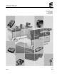
Warranty Manual Espar Products, Inc. Tel: 905.670.0960 800.387.4800 Fax: 905.670.0728 www.espar.com 1 QSF-60 02.2014 Rev.
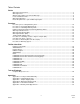
Table of Contents Policies Warranty Policy Overview ............................................................................................................................. 3 Warranty Period ............................................................................................................................................ 4 What IS and IS NOT covered under Warranty? ............................................................................................ 5 Heater Identification Plate .......
Warranty Policy Overview The purpose of Espar warranty is to ensure that the end-user (customer) of Espar Products is satisfied with the quality of their purchase. In order to provide customer satisfaction, Espar stands behind its products as they leave Espar’s control. This Espar Warranty Manual and all policies and procedures within it, supersedes all previous warranty manual revisions. It will remain valid until a new manual is released or until further notice.
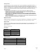
Warranty Period The warranty period of a heater is specified in years or in heater operating hours, beginning from the date of installation, whichever is reached first. Refer to “What IS and IS NOT covered under Warranty” on Page 5 of this manual. If the installation date is not made known to Espar by registering the heater within thirty (30) days of installation, or by providing proof of installation date at time of warranty claim (i.e.
What IS and IS NOT Covered Under Warranty The purpose of Espar Warranty is to provide the end user (customer) of Espar heaters with protection from defects in material and workmanship. A. Items covered under warranty include: PARTS 1. Timers, thermostats, mini-controllers or other electronic temperature control products provided by Espar 2. Electronic control units (ECU’s) 3. Glow pins 4. Fuel metering pumps 5. Heat exchangers and / or combustion chambers (burner) 6. Air blowers 7. Coolant pumps 8.
. Diagnosis or repairs completed when cause of the problem or failure is due to electrical system problems outside the heater, excessive engine debris or empty fuel tanks or poor quality fuel. 7. Deterioration due to normal wear, corrosion, abuse, damage, accident, improper storage or operation. 8. Costs incurred through an incorrect diagnosis, poor performance of the repair. This also applies to corrections of installations that did not meet Espar specifications.
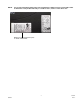
NOTE: It is strongly advised that during the heater installation the duplicate heater serial number label is affixed in a clearly visible and easily accessible location, such as on the driver door. Duplicate heater identification plate or “serial number label” 7 QSF-60 02.2014 Rev.
Warranty Registration A blue warranty registration notification is shipped with every heater. Please note there are several important reasons why the warranty should be registered. If a warranty registration is not received by Espar, the heater warranty period begins on the date the heater is shipped from Espar’s North American warehouse.
Dealer Requirements to Perform Warranty Repairs To conduct warranty repairs and submit warranty claims, the following criteria must be met: 1. Possess and maintain certified technician’s who have undergone Espar technical training (installation, diagnosing and troubleshooting) and warranty training. 2. Possess all tools required to install, maintain and service Espar products as outlined in the ‘Tools and Equipment’ section of Espar manuals. 3.
Procedure Prior to Starting Warranty Work As a member of the Espar distribution organization, you are expected to stand behind your work. This includes properly specifying and installing heaters and instructing your customers on the proper operation and maintenance of the heater and all related components or accessories. All heater technical manuals are available for download at Espar’s website, www.espar.com.
Procedure for Performing Warranty Work As a member of the Espar distribution organization you are trained in the installation, troubleshooting and repair of Espar heaters and systems and you have all of the necessary tools required to properly diagnose heater functions. Technical publications such as Technical Descriptions, Troubleshooting Guides and Parts Manuals are available by downloading directly from Espar’s website, www.espar.com.
Procedure for Submitting Warranty Claims IMPORTANT NOTE: After the warranty work has been performed and the heater is operating properly and it has been determined that the problems were truly warranty problems and not due to improper application specification, installation or operation; the procedure is as follows: 1. Affix the Espar Warranty Tag to all claimed parts.
6. Each claim automatically receives thirty (30) minutes of troubleshooting, Operation Code A and thirty (30) minutes for heater function testing, Operation Code D. 7. In ‘Parts Required for Repair’ section, indicate the quantity and choose Espar part number and description. 8. Choose the applicable operation code and labor times as per the applicable Flat Rate Labor Guide. Example: The AIRTRONIC D2 appears to start normally but then it shuts down and attempts to restart.
Espar’s Internal Procedure for Processing Warranty Claims Espar will make every effort to process warranty claims promptly providing all information is provided as set out in this manual. Thus, Espar is committed to issuing credit for processed warranty claims within thirty (30) days of receiving back the requested parts. Warranty Notification Form It is the dealer’s responsibility to respond to the warranty notice (Appendix D) within ten (10) business days.
Warranty Evaluation (WE) Every claimed part must be tagged and held for thirty (30) days following the submission of a warranty claim. During this time frame Espar may request that a part or heater be returned to Espar for evaluation. In this case the following procedures will apply: 1.
“Always Repair Heater” Policy Espar and Eberspaecher have an “Always Repair Heater” policy. In the case that a Main Service Distributor or Dealer has difficulty in diagnosing and repairing a heater they should contact Espar’s Technical Department for further assistance. After consulting with Espar and providing that it is within its warranty period and Espar has deemed it necessary to have the heater returned, Espar will issue an RR#. This will authorize the heater to be shipped to Espar for repair.
New Defective Parts or Heaters (when they are NOT covered under warranty) If a new part or heater is determined to be defective by visual inspection, or found to be functionally defective immediately, prior to installation, it should be returned to Espar using a Return Goods Authorization Policy (RGA). New defective parts or heaters can not be claimed as warranty. Procedure for Returning Defective Goods (RGA) 1.
Procedure for Warranty Appeal It is Espar’s intent to close all claims within thirty (30) days after parts are returned and claim process is completed. The warranty appeal must be filed within thirty (30) days of claim rejection issue date in order to receive consideration for reversal. IMPORTANT NOTE: Appeals will not be considered for claims that have aged beyond thirty (30) days of final rejection issue date and closed permanently. Warranty Appeal Process 1.
Espar Flat Rate Labor Guide This Flat Rate Labor Guide has been developed and based on the worldwide experience of Espar and Eberspaecher service centers. This guide is organized by heater model in order of heat output. When submitting a warranty claim, it is mandatory to log a detailed description of the repair. The description you provide should correspond with the fault codes indicated. It is imperative to verify replaced parts as failed parts.
AIRTRONIC 2 / 4 For Heater Model Numbers: 12V AIRTRONIC D2 25 2069 AIRTRONIC D4 25 2113 AIRTRONIC B4 20 1812 Diagram Reference Number 24V 25 2070 25 2114 Part Description Operation A. Troubleshoot B. Components Replaced with Heater Installed 1 Electronic Control Unit (ECU) 2 Combi-Sensor (Overheat / Flame) 3 Glow Pin with Tool 4 Fuel Metering Pump 5 Mini-Controller 6 Thermostat 7 Rheostat 8 7-Day Timer Digi-Max 9 Main Wire Harness 9 Main Wire Harness 10 Heat Exchanger / Burner C.
AIRTRONIC 2 / 4 21 QSF-60 02.2014 Rev.
B/D1LC Compact For Heater Model Numbers: 12V B1LC Compact 20 1766 D1LC Compact 25 1976 Diagram Reference Number Part Description Operation A. Troubleshoot B.
B/D1LC Compact 23 QSF-60 02.2014 Rev.
B/D3LC Compact For Heater Model Numbers: 12V D3LC Compact 25 1981 Diagram Reference Number 24V Part Description Operation A. Troubleshoot B. Components Replaced with Heater Installed 1 Electronic Control Unit (ECU) 2 Fuel Metering Pump 3 Mini-Controller 4 Thermostat 5 Rheostat 6 7-Day Timer 7 Seal, Glow Plug 8 Battery Wire Harness 9 Switch Wire Harness 10 Fuel Metering Pump Wire Harness 11 Main Wire Harness 11 Main Wire Harness C.
B/D3LC Compact 25 QSF-60 02.2014 Rev.
AIRTRONIC 5 For Heater Model Numbers: 12V AIRTRONIC B5 20 1859 AIRTRONIC D5 25 2361 Diagram Reference Number 24V 25 2362 Part Description Operation A. Troubleshoot B. Components Replaced with Heater Installed 1 Remote Temperature Sensor 2 Fuel-Metering Pump 3 Mini-Controller 4 Thermostat 5 Rheostat 6 7 Day Timer Digi-Max 7 Main Wire Harness 7 Main Wire Harness Replace Replace Replace Replace Replace Replace Replace Repair Replace C.
AIRTRONIC 5 27 QSF-60 02.2014 Rev.
D8LC For Heater Model Numbers: 12V D8LC 25 1890 Diagram Reference Number 24V 25 1891 Part Description Operation A. Troubleshoot B.
D8LC 29 QSF-60 02.2014 Rev.
HYDRONIC 4 / 5 SC (Integrated Coolant Pump, Integrated Fuel Metering Pump) For Heater Model Numbers: 12V HYDRONIC D5 25 2219 Diagram Reference Number Part Description Operation A. Troubleshoot B. Components Replaced with Heater Installed 1 Electronic Control Unit (ECU) 2 Push / Pull Switch 3 7-Day Timer 4 Thermostat Multi-Max 5 Main Wire Harness 5 Main Wire Harness C.
HYDRONIC 4 / 5 SC (Integrated Coolant Pump, Integrated Fuel Metering Pump) 31 QSF-60 02.2014 Rev.
HYDRONIC 4 / 5 SC (Integrated Coolant Pump, External Fuel Metering Pump) For Heater Model Numbers: 12V HYDRONIC D4 20 1824 HYDRONIC B5 20 1820 HYDRONIC D5 25 2325 Diagram Reference Number 24V 25 2147 Part Description Operation A. Troubleshoot B. Components Replaced with Heater Installed 1 Electronic Control Unit (ECU) 2 Fuel Metering Pump 3 Push / Pull Switch 4 7-Day Timer 5 Thermostat Multi-Max 6 Main Wire Harness 6 Main Wire Harness C.
HYDRONIC 4 / 5 SC (Integrated Coolant Pump, External Fuel Metering Pump) 33 QSF-60 02.2014 Rev.
HYDRONIC 5 S (External Coolant Pump, External Fuel Metering Pump) For Heater Model Numbers: 12V HYDRONIC B5 20 1819 HYDRONIC D5 25 2217 Diagram Reference Number 24V 24V 25 2146 25 2218 Part Description Operation A. Troubleshoot B. Components Replaced with Heater Installed 1 Electronic Control Unit (ECU) 2 Coolant Pump 3 Fuel Metering Pump 4 Push / Pull Switch 5 7-Day Timer 6 Thermostat Multi-Max 7 Main Wire Harness 7 Main Wire Harness C.
HYDRONIC 5 S (External Coolant Pump, External Fuel Metering Pump) 35 QSF-60 02.2014 Rev.
HYDRONIC 5 Z (No Coolant Pump, External Fuel Metering Pump) For Heater Model Numbers: 12V HYDRONIC D5 25 2216 Diagram Reference Number Part Description Operation A. Troubleshoot B. Components Replaced with Heater Installed 1 Electronic Control Unit (ECU) 2 Fuel Metering Pump 3 Push / Pull Switch 4 7-Day Timer 5 Thermostat 6 Main Wire Harness 6 Main Wire Harness Replace Replace Replace Replace Replace Repair Replace C.
HYDRONIC 5 Z (No Coolant Pump, External Fuel Metering Pump) 37 QSF-60 02.2014 Rev.
HYDRONIC II 5E (External Coolant Pump, External Fuel-Metering Pump) For Heater Model Numbers: HYDRONIC B5S HYDRONIC D5S Diagram Reference Number 12V 20 1904 25 2526 Part Description Operation A.
QSF-60 02.2014 Rev.
HYDRONIC 10 For Heater Model Numbers: 12V HYDRONIC 10 25 2160 Diagram Reference Number 24V 25 2227 Part Description A. Troubleshoot B. Components Replaced with Heater Installed 1 Electronic Control Unit (ECU) 2 Fuel Metering Pump 3 Push / Pull Switch 4 7-Day Timer 5 Thermostat Multi-Max 6 Main Wire Harness 6 Main Wire Harness Operation Replace Replace Replace Replace Replace Replace Repair Replace C.
HYDRONIC 10 41 QSF-60 02.2014 Rev.
HYDRONIC MII For Heater Model Numbers: 12V HYDRONIC M8 25 2470 HYDRONIC M10 25 2434 HYDRONIC M12 25 2472 HYDRONIC M12 25 2596 Diagram Reference Number 24V 25 2471 25 2435 25 2473 Part Description A. Troubleshoot B. Components Replaced with Heater Installed 1 Coolant Pump 2 O-Ring, Coolant Pump 3 Relay Wire Harness 4 Fuel Metering Pump 5 Fuel Metering Pump Wire Harness 6 Push / Pull Switch 7 7-Day Timer 8 Programmable Timer Multi-Max 9 Main Wire Harness 10 Main Wire Harness C.
HYDRONIC MII 43 QSF-60 02.2014 Rev.
HYDRONIC 16 / 24 / 30 / 35 For Heater Model Numbers: 24V HYDRONIC 35 25 1819 Diagram Reference Number Part Description A. Troubleshoot B.
HYDRONIC 16 / 24 / 30 / 35 45 QSF-60 02.2014 Rev.
HYDRONIC LII For Heater Model Numbers: HYDRONIC L16 25 2486 HYDRONIC L24 25 2487 HYDRONIC L30 25 2488 HYDRONIC L35 25 2489 Diagram Reference Number 25 2599 Part Description A. Troubleshoot B. Components Replaced with Heater Installed 1 Coolant Pump 2 Overheat Sensor 3 Temperature Sensor 4 Push / Pull Toggle Switch 5 7-Day Timer 6 Spare Part Kit, Coolant Pump Multi-Max 7 Main Wire Harness 7 Main Wire Harness 8 Combustion Air Inlet Hood 9 Internal Main Wire Harness C.
HYDRONIC LII 47 QSF-60 02.2014 Rev.
Tools and Equipment Generally, standard shop tools are required for the installation and repair of Espar heaters. However, there are a few additional tools required for efficient troubleshooting and repair. All required tools are listed below.
Computer Diagnostic Tool – EDiTH The following overview is to help you understand the capability of different diagnostic hardware. Available are: Diagnostic Unit, EDiTH Basic and EDiTH Expert.
APPENDIX A The Espar Limited Warranty Espar Products, Inc. (“Espar”) warrants its heaters (the “Products”) to be free from defects in materials and workmanship, subject to the terms below.
APPENDIX B Sample Warranty Tag 51 QSF-60 02.2014 Rev.
APPENDIX C Sample Warranty Shipping Label 52 QSF-60 02.2014 Rev.
APPENDIX D Warranty Notification Form Warranty Claim # Date Serial # Model # Warranty Claim is ON HOLD: Additional information is required by Espar to process the warranty claim. Please submit the following information to Espar’s Warranty Department within 10 business days from the date on this form. Installation documentation required to prove applicable warranty period (as warranty was not registered). Further technical information required to support repair.
APPENDIX E Technician’s Checklist Work Order: Heater Model: Serial Number: Technician: EDiTH Information ITEM CHECK AF F1 F2 F3 Overall Heater Run Time: F4 F5 Number of Starts: Installation position on vehicle Fuel pump mounting position Fuel quantity test (before removal) Unit is boxed? YES CHECK PERFORMED FOUND (YES / NO) ELECTRICAL SYSTEM NO ACTION TAKEN Are connections tight and free of corrosion? Has proper gauge wiring been used for the length and amperage requirements? Have any fuses /
APPENDIX F WARRANTY CLAIM APPEAL Customer Information Customer Address, City Province / State Country Postal / Zip Code Phone / Fax Submitted by Information Submitted by Email Date of Appeal MM DD YY Claim Information Claim # WE # (if given) Reason for Appeal Comments: NOTE: Warranty appeal should be done within 30 days after receiving the outcome of the warranty claim. QSF-WD013 Rev. Rel 55 QSF-60 02.2014 Rev.
Espar Products, Inc. 800.387.4800 905.670.0960 905.670.0728 Fax www.espar.com A member of the Worldwide Eberspaecher Group of Companies 56 QSF-60 02.2014 Rev.