www.eberspaecher.com J.Eberspächer GmbH & Co. KG Eberspächerstraße 24 D-73730 Esslingen Telefon Hotline 0800 1 23 43 00 Fax Hotline 01805 26 26 24 info@eberspaecher.com VHM/MS 12/08 Bech 1.0 Technical data : +/- 10% Subject to modification, errors possible. Printed in Germany. Printed on chlorine-free paper. The compass heading is heat. Eberspächer marine heaters. Marine catalogue — information, technology, tips.
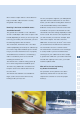
The Eberspächer marine catalogue is intended to be used for supporting dockyard and Eberspächer service partners when figuring out which heater system to use and install, as well as for giving the ship owner important instructions for using the heater system. On the next several pages, you will find information on air and water heating units as well as operating controls and accessories.
1 Answers to frequently asked questions 6 2 Product information on air heaters and operating controls Component rating, installation planning for air heaters Combustion air system, exhaust routing 16 3 Airtronic D2 product information Air system, combustion air system, exhaust routing, Fuel feed line 24 4 Airtronic D3 product information Air system, combustion air system, exhaust routing, Fuel feed line 32 5 Airtronic D4/D4Plus product information Air system, combustion air system, Exhaust rout
An outstanding choice: Your Eberspächer heater No matter what kind of engine or other heat sour- Feeling perfectly comfortable requires ces are being used, Eberspächer heaters create perfect coordination a cosy atmosphere on board.
Bring some first-class comfort on board! Eberspächer offers a wide range of air Each air heater unit can be controlled using and water heaters for every size of boat a thermostat that regulates the heat separa- for seasonal and year-round use. tely for each room. Fuel that is either already available, or is The air heater units can be operated using easy to obtain—preferably, safe diesel oil— recirculated or fresh air. We recommend the is used on board. fresh-air operation in particular.
Answers to your frequently asked questions What will I actually get for my money? Which system is right for me: With an Eberspächer stationary heater, you water or air? are getting a premium product that has been That depends mainly on the amount of time you painstakingly manufactured according to will need the heat and how you use it. Air heaters the highest quality and safety standards.
We’ve listed a couple of basic criteria below to The only exceptions might be: your Eberspächer help you decide. A diesel heater is usually specialist will have to determine on site which integrated in the design. heater you will need for working boats that have to be heated under bitterly cold conditions. How big is the boat and which rooms Sailboats usually have less interior volume than should be heated? motorboats.
Operation How do you operate the stationary heater? uses only 0,62 l of diesel per hour at its highest Convenient controls are used to operate these setting. But on the other hand, it uses just heaters. Mini-controllers are primarily used to 0.27 l/h on its lowest setting. Our air heaters, operate air heaters; timers or remote control e.g. the Airtronic D4, only need 0.51 l/h at the units are used for water heaters. Our Calltronic most to warm up your cabins.
heater air must be drawn in from outside In addition, the diesel heater must get its fuel at a point you are absolutely sure is free from from a separate diesel tank that meets code for any possible gasoline fumes and exhaust. all the generally applicable, local regulations 1 regarding diesel tanks in boats. 2 gasoline-powered boat? Does a stationary heater need AC 3 It is basically possible to install a diesel heater mains power (230 V)? in a gasoline-powered boat. In this instance, the No.
Safety Does a stationary heater make noise? Which regulations do I have to follow Well, by their very nature of course all stationary when operating a heater? heaters make combustion noises when they Legal Regulations are operating. But they are so minimal that Legal guidelines vary from region to region in our stationary heaters are approved for day terms of governing the design, installation and and night operation. For boat installation in operation of heaters in boats.
CE certification How long is the warranty on new heaters? Since June 16, 1998, every newly manufactured Eberspächer warrants all its products for sports boat between 2.5m and 24m long—inclu- 24 months. ding its system components—has to meet the CE identification requirements. For heater Does a stationary heater need special installation, this means the following: service? • That the heater is labelled with CE identification No. Our products are maintenance-free.
Important installation and safety information Using the heater • An air heater’s heat exchanger is a component The heater may only be used and operated subjected to a high degree of stress, it has to for the specified purposes for which it is manu- be replaced ten years after the heater was initi- factured, and in accordance with the “Technical ally put into operation. In addition, the date of Description” that accompanies each heater.
The following actions are not permitted • Only those control devices approved by • Changing or altering heater-related components. Eberspächer GmbH & Co. KG may be used for • Use of non-OEM parts not approved by operating heaters. Using other control devices Eberspächer GmbH & Co. KG. • Deviations from legal, safety and/or function- where inflammable vapours, fumes or dust tion, which are given in the installation and/or can form—e.g. near a fuel depot, coal yard, operating instructions.
• In particular, reserve fuel canisters, oil cans, Emergency cut-off — EMERGENCY/OFF spray cans, gas cartridges, fire extinguishers, The following must be done in the event of cleaning rags, articles of clothing, paper, etc. an emergency cut-off — EMERGENCY/OFF — must not be stored or transported on or while operating the heater: next to the heater. • Pull fuse or • The heater must be turned off before refuelling. • Defective fuses may only be replaced with fuses bearing the specified fuse rating.
1 The environment Waste disposal management Certification The high quality of Eberspächer products is Disposing of materials the key to our success. In order to ensure this Old equipment, defective components quality, we have organized all of the work proces- and packing material can be correctly sorted ses in our company in terms of quality manage- separately, so that if necessary, all parts can ment (QA).
The right air heater for every need Skippers are individualists—and every boat has its And your selection from the Eberspächer line of pro- own special quirks and characteristics that an ducts is just as great. With heater outputs of 850 Eberspächer marine heater needs to cope with: to 8,000 W for spaces up to 70m3, you will definitely smaller boats require different solutions than find what you want. Stop by and talk it over with your 20-meter yachts.
Superb performance in any size Eberspächer heaters can be retrofitted to your boat Take a good look at our broad range of products and quickly and easily. So it’s never too late to indulge the many different ways you can use them. And then yourself and your crew in a real plus in comfort! let our competent experts handle the installation.
The benefits of Eberspächer heaters: Power stage for rapid, direct heating Continuously variable temperature preselection Suitable for fresh-air operation Nearly silent operation Can be used purely for ventilation on warm days Example of an installation: In this example, the Airtronic is installed on the port side in the ship’s locker. Fresh air is drawn in through the cockpit, the hot air outlet is located next to the companionway, and the exhaust line exits at the stern of the boat in the transom.
System accessories for your complete, customized solutions: 1 Eberspächer offers a wide range of premium requirements for use on smaller boats and accessories that are coordinated to complement sea-going yachts. You will find all of these parts each other, and that will meet all the particular in the marine catalogue starting on page 54.
Hot air system and parts Component rating General instructions on the heater air system and the parts Component rating General rule of thumb: Parts for conducting heat can also be installed on the heater. Each part has a parts Component rating, which reduces the heated air output.
Example for calculating hot air routing: Airtronic D2 Ø 60 mm hose diameter unit number 6 1 No. Name 1 Protective grille and connector ø 60 mm 1.7 2 Flexible tube ø 60 mm, 0.3 m long 0.3 3 Flexible tube ø 60 mm, 1 m long 1,0 4 Hood straight ø 60 mm 5 90° bend flexible tube ø 60 mm 1.2 6 Rotatable vent 1.4 Sum of part Component rating 5.6 2 Part Component rating 3 4 0 5 6 The sum of the part Component rating = 5.
Installation location Please note! Installation location You don’t need to sacrifice any cabin space to install these heaters because the units can be housed in any space that is well ventilated to the outside, e.g. in the boat’s locker, the ship’s hold and storage space. If installing the heater in the engine compartment, metal fuel lines or fire-retardant hoses (in accordance with DIN EN ISO 7840) must be used. When the boat heels, bilge water must not wash over the heater unit.
Combustion air system Exhaust gas routing Combustion air must be drawn from a well-ventilated area at atmospheric pressure (not from the cabin). In sailboats, the exhaust gas routing is taken to the transom, and in motorboats to the side hull. The exhaust gas routing must be insulated so that the surface temperature does not exceed 80° C. Routing the exhaust gas through a cabin can only be done through a pipe made of stainless steel.
Airtronic D2 Technical data Airtronic D2 Voltage 12/24 V Heating levels for heat flow W Air throughput Electrical power consumption Power 2,200 Large 1,800 Medium 1,200 Small 850 m3/h 90 75 52 36 W 34 22 12 8 Fuel consumption l/h 0.28 0.23 0.15 0.10 Dimensions LxWxH mm Weight kg 310x115x122 2.
Product information Item parts list Heater scope of delivery Airtronic D2 heater Metering pump The following must also be ordered: Parts conducting air Parts conducting exhaust and combustion air Fasteners Parts carrying fuel Electrical parts Controls and accessories Order numbers starting on page 1-2 3-12 13-21 22-29 23-32 33-36 37-39 54 98 114 106 1 2 3 4 In sailboats, the heater is usually installed in the ship’s locker.
Airtronic D2 Parts for air routing Unit Component rating for the heater • If the air vent hood = ø 60 mm, then the heater unit Component rating = 6. • If the air vent hood = ø 75 mm, then the heater unit Component rating = 12. This diagram shows how the most important parts are used for routing the air in a single-duct heater system or in a dual-duct heater system. Single-duct heater means: A hot-air duct goes either to or from the heater. The part Component rating listed under “single duct” apply.
Product information Part Component rating for parts that conduct air Part Component rating for the heater with air vent hood ø 60 mm – unit Component rating for the heater = 6 No. Part Component rating Single duct Dual duct Name 1 2 Grille with Hose fitting 1.7 0.6 3 Flexible tube ø 60 mm, per m 1 0.3 3a Flexible tube with 90° bend ø 60 mm 1.2 0.8 4 Grille ø 60 mm 0 – 5 Hood ø 60 mm 0 – 6 Swiveling hood ø 60 mm 4.5 – 7 Elbow pipe ø 60 mm, 90° 4.1 0 8 T-branch – 0.
Airtronic D2 Parts for routing combustion air No. 1 2 3 Name Hose clamp Silencer for front left Hose connecting pipe ø 25 mm No. 4 5 Name Flexible tube ø 25 mm Boat hull opening for front left Parts for routing the exhaust No. 1 2 3 4 5 28 Name Pipe clamp 90°-angle exhaust pipe ø 24/30 mm 90°-angle exhaust pipe ø 24/30 mm with drain Flexible spiral tube ø 30 mm Condensate drainage No.
Product information Fuel supply In most cases, it is recommended that the fuel be drawn through a separate tank connection and that it be installed in the fuel tank (for metal tanks only). If installing a separate tank connection in the fuel tank is not an option, then fuel must be drawn through a T-fitting that is connected to the fuel supply line that runs from the fuel tank to the motor.
Airtronic D3 Technical data Airtronic D3 Voltage 12 V Heating levels of heat flow W Airthroughput Electrical power consumption (operation) Power 3000 Large 2.200 Medium 1.600 Small 900 m3/h 130 100 80 52 W 24 16 10 7 Fuel consumption l/h 0.38 0.28 0.20 0.11 Dimensions LxWxH mm Weight kg 376x140x150 4.
Product information Item parts list Heater scope of delivery Airtronic D3 heater Metering pump The following must also be ordered: Parts conducting air Parts conducting exhaust gas and combustion air Fasteners Parts carrying fuel Electrical parts Controls and accessories Order numbers starting on page 1-2 3-10 11-19 20/27 21-30 31-34 35-37 54 98 114 106 1 2 3 4 In sailboats, the heater is usually installed in the ship’s locker.
Airtronic D3 Electrical parts for air ducts • The unit Component rating for the heater that includes the ø 75 mm air vent hood is 3. • If the air vent hood = ø 90 mm, then the heater unit Component rating = 10. Single-duct heater means: A hot-air duct goes either to or from the heater. The part Component rating listed under “single duct” apply. This diagram shows how the most important parts for routing the air are used in a single-duct heater system or in a dual-duct heater system.
Product information Part Component rating for parts that duct air Airtronic D3 with air vent hood ø 75 mm = unit Component rating 3/ø 90 mm = unit Component rating 10 Part Component rating Single ductct Dual ductct ø 75 / ø 90 ø 75 / ø 90 1/– 0.2 / 0.3 1/– 0.2 / 0.4 No. Name 1 1a Flexible tube ø 75 mm, each m Flexible tube with 90°- bend ø 75 mm 2 Hose fitting ø 75 mm, metal 3 Grille –/– –/– 4 Grille ø 75 mm –/– –/– 5 Intake silencer ø 75 mm 1 / 0.
Airtronic D3 Parts for ducting combustion air No. 1 2 3 Name Hose clamp Silencer for front left Hose connecting pipe ø 25 mm No. 4 5 Name Flexible tube ø 25 mm Boat hull opening for front left Parts for routing the exhaust No. 1 2 3 4 5 34 Name Pipe clamp 90°-angle exhaust pipe ø 24/30 mm 90°-angle exhaust pipe ø 24/30 mm with drain Flexible spiral tube ø 30 mm Condensate drainage No.
Product information Fuel feed line In most cases, it is recommended that the fuel be drawn through a separate tank connection and that it be installed in the fuel tank (for metal tanks only). If installing a separate tank connection in the fuel tank is not an option, then fuel must be drawn through a T-fitting that is connected to the fuel supply line that runs from the fuel tank to the motor.
Airtronic D4/D4 Plus Technical data Airtronic D4 Voltage V Heating levels of heat flow W Airthroughput Electrical power consumption (operation) Airtronic D4 Plus 12/24 12/24 Power 4.000 Large 3.000 Medium 2.000 Small 900 Power 4.000 Large 3.000 Medium 2.000 Small 900 m3/h 160 130 95 55 155 120 86 45 W 40 24 13 7 55 30 13 7 Fuel consumption l/h 0.51 0.38 0.25 0.11 0.51 0.38 0.25 0.11 Dimensions LxWxH mm Weight kg 376 x140 x150 376 x140 x150 4.5 4.
Product information Item parts list Heater scope of delivery Airtronic Airtronic D4 / D4 Plus Heater Metering pump The following must also be ordered: Parts conducting air Parts conducting exhaust and combustion air Fasteners Parts carrying fuel Electrical parts Controls and accessories Order numbers starting on page 1-2 3-10 11-19 20 21-30 31-34 35-37 54 98 114 106 1 2 3 4 In sailboats, the heater is usually installed in the ship’s locker.
Airtronic D4/D4Plus Parts for air ducts Unit Component rating for the Airtronic D4 heater • If the air venthood = ø 75 mm, then the heater unit Component rating = 3. • If the air vent hood = ø 90 mm, then the heater unit Component rating = 10. Unit Component rating for the Airtronic D4Plus heater • If the air vent hood = ø 75 mm, the heater has a unit Component rating of 8 for ambient, 10 for fresh-air operation. • If the air vent hood = ø 90 mm, then the heater unit Component rating = 15.
Product information Part Component rating for parts that conductair Airtronic D4 with air vent hood ø 75 mm = unit Component rating 3, ø 90 mm = unit Component rating 10 Airtronic D4 Plus with air vent hood ø 75 mm = unit Component rating 8/10, ø 90 mm = unit Component rating 15 Part Component rating Single duct Dual duct ø 75 / ø 90 ø 75 / ø 90 1/– 0.2 / 0.3 1/– 0.2 / 0.4 No.
Airtronic D4/D4Plus Parts for ducting combustion air No. 1 2 3 Name Hose clamp Silencer for front left Hose connecting pipe ø 25 mm No. 4 5 Name Flexible tube ø 25 mm Boat hull opening for front left Parts for routing the exhaust No. 1 2 3 4 5 40 Name Pipe clamp 90°-angle exhaust pipe ø 24/30 mm 90°-angle exhaust pipe ø 24/30 mm with drain Flexible spiral tube ø 30 mm Condensate drainage No.
Product information Fuel feed line In most cases, it is recommended that the fuel be drawn through a separate tank connection and that it be installed in the fuel tank (for metal tanks only). If installing a separate tank connection in the fuel tank is not an option, then fuel must be drawn through a T-fitting that is connected to the fuel supply line that runs from the fuel tank to the motor.
Airtronic D5 Technical data Airtronic D5 Voltage V 12/24 Power 5,500 large 4,800 medium 2,700 small 1,600 m3/h 233 210 160 130 W 85 80 35 25 Fuel consumption l/h 0.66 0.58 0.34 0.19 Dimensions LxWxH mm Weight kg Heating levels of heat flow W Airthroughput Electrical power consumption (operation) 530 x170 x185 9.
Product information Item parts list Heater scope of delivery Airtronic D5 heater Metering pump The following must also be ordered: Parts conducting air Exhaust gas and combustion air system parts Fasteners Parts conducting fuel Electrical parts Controls and accessories Order numbers starting on page 1-2 3-12 13-21 22-29 23-32 33-36 37-39 54 98 114 106 1 2 3 4 In sailboats, the heater is usually installed in the ship’s locker.
Airtronic D5 Electrical parts for air ducts Unit Component rating for the heater = 10 This diagram shows how the most important parts are used for routing the air in a single-duct heater system or in a dual-duct heater system. Single-duct heater means: A hot-air duct goes either to or from the heater. The part Component rating listed under “single duct” apply. Dual-duct heater means: The hot-air duct branches into two ducts after the heater.
Product information Part Component rating for parts that conduct air Unit Component rating heater = 10 No. Name Single duct Dual ductct 1 Grille 0.5 0.25 2 Hose fitting ø 100 mm, metal 0 0 3 Flexible tube ø 100 mm, each m 0.5 0.25 Flexible tube with 90° bend ø 100 mm 0 0 4 Grille or ring ø 90/100 mm 0 – 5 Hose fitting ø 90 mm, metal 0 0 6 Flexible tube ø 90 mm, each m 1 0.3 – Flexible tube with 90°- bend ø 90 mm 0.25 0 7 Silencer ø 90 mm 0,6 0.
Airtronic D5 Parts for ducting combustion air No. 1 2 3 Name Hose clamp Silencer for front left Hose connecting pipe ø 25 mm No. 4 5 Name Flexible tube ø 25 mm Boat hull opening for front left Parts for exhaust routing No. 1 2 3 4 5 46 Name Pipe clamp 90°-angle exhaust pipe ø 24/30 mm 90°-angle exhaust pipe ø 24/30 mm with drainage Flexible spiral tube ø 30 mm Condensate drainage No.
Product information Fuel feed line In most cases, it is recommended that the fuel be drawn through a separate tank connection and that it be installed in the fuel tank (for metal tanks only). If installing a separate tank connection in the fuel tank is not an option, then fuel must be drawn through a T-fitting that is connected to the fuel supply line that runs from the fuel tank to the motor.
Air Heater D8LC Technical data D8L C Voltage 12/24 V large 8,000 small 3,500 m3/h 250 250 W 115 380 Fuel consumption l/h 1.0 0.
Product information Item parts list Heater scope of delivery Heater D8LC The following must also be ordered: Electrical parts Exhaust gas and combustion air system parts Parts conducting air Parts conducting fuel Order numbers starting on page 1-8 9 10-17 18-22 23-31 98 54 106 1 2 3 4 In sailboats, the heater is usually installed in the ship’s locker. The combustion air is drawn in from the locker and the exhaust gases are fed to the outside through the transom.
Air heater D8LC Electrical parts for air ducts Unit Component rating for the heater = 8 This diagram shows how the most important parts are used for routing the air in a single-duct heater system or in a dual-duct heater system. Single-duct heater means: A hot-air duct goes either to or from the heater. The part Component rating listed under “single duct” apply. Dual-duct heater means: The hot-air duct branches into two ducts after the heater.
Product information Part Component rating for parts that direct air through ducts Unit Component rating for the heater = 8 No. Name Part Component rating Single ductct Dual ductct 1 Grille ø 100 mm 0.1 – 2 Flexible tube ø 100 mm, each m 90°- bend of flexible tube ø 100 mm 1.0 0.5 0.25 0.15 3 Hose fitting ø 100 mm, metal 0.18 0.1 4 Grille, painted ø 100 mm Grille, nickel-plated ø 100 mm 0.18 0.18 0.1 0.1 5 Exhaust silencer ø 100 mm 1.1 0.
Air heater D8LC Parts for directing combustion air through ducts No. 1 2 3 Name Flexible tube ø 30 mm Hose clamp 3 boat hull openings for combustion air Parts for routing the exhaust No. 1 2 3 4 5 52 Name Exhaust elbow pipe ø 42/40 mm with drainage Flexible spiral tube ø 40 mm Pipe clamp Condensate drain Fitting No.
Product information Fuel feed line In most cases, it is recommended that the fuel be drawn through a separate tank connection and that it be installed in the fuel tank (for metal tanks only). If installing a separate tank connection in the fuel tank is not an option, then fuel must be drawn through a T-fitting connection that is connected to the fuel supply line that runs from the fuel tank to the motor.
~ Check the connector diameter i/d i/d i/d i/d i/d = = = = = ø ø ø ø ø 50 60 75 90 100 mm mm mm mm mm ~ ~ ~ ~ ~ ~ ~ ~ D 8LC Airtronic D5 Airtronic D4 Plus Air hose attachment page 115 Airtronic D4 Airtronic D2 1. Flexible pipe (running meter), APK, heater air duct in the interior compartment Airtronic D3 Parts conducting air Order no. 10 10 10 10 10 2114 2114 2114 2114 2114 29 31 34 37 38 00 00 00 00 00 00 00 00 00 00 2. Silencer (alum.
D 8LC Airtronic D5 Airtronic D4 Plus Airtronic D4 Airtronic D3 Airtronic D2 4. Air vent rotatable Order no. ~ Check the connector diameter d = ø 60 mm, D = ø 97 mm black 20 1577 89 06 00 ~ ~ ~ 5. Air vent rotatable ~ Check the connector diameter * incl.
D = ø 93 mm, L = ø 75, d = 60 mm D 8LC Airtronic D5 Airtronic D4 Can be combined with item 8, 10-12 Airtronic D3 Airtronic D2 7. Grille Airtronic D4 Plus Parts conducting air Order no. 22 1000 01 00 01 plastic, black D = ø 132 mm, L = ø 120, d = 95 mm 25 1226 89 05 00 vernickelt D = ø 132 mm, L = ø 120, d = 100 mm 25 1729 89 00 05 plastic, black 8.
~ Check the connector diameter d = ø 50 mm, D = ø 97 mm, L = ø 75 d = ø 60 mm, D = ø 97 mm, L = ø 75 ~ D 8LC Airtronic D5 Airtronic D4 Plus Airtronic D4 Can be combined with item 7 Airtronic D3 Airtronic D2 10. Hose fitting Order no. ~ ~ ~ 20 1575 80 08 01 20 1577 89 06 01 ~ ~ ~ ~ 251226 89 00 40 11. Hose fitting Metal Can be combined with item 7 ~ Check the connector diameter 1 2 12.
D 8LC Airtronic D5 Airtronic D4 Airtronic D3 Airtronic D2 14. Hood Airtronic D4 Plus Parts conducting air Order no. d = ø 90 mm 25 1729 01 09 00 d d d d 22 22 22 22 15. Swiveling hood = = = = ø ø ø ø 60 75 75 90 mm mm mm mm 1000 1000 1000 1000 01 01 01 01 00 00 00 00 20 28 22 23 16.
~ Check the connector diameter i/d = ø 60 mm, o/d = ø 60 mm i/d = ø 75 mm, o/d = ø 75 mm ~ ~ ~ D 8LC Airtronic D5 Airtronic D4 Plus Airtronic D4 Airtronic D3 Airtronic D2 17. Elbow pipe, 90° Order no. 25 1688 89 00 01 25 1482 89 00 05 18. Ring 1 ~ Check the connector diameter i/d = ø 60 mm, o/d = ø 75 mm i/d = ø 75 mm, o/d = ø 90 mm i/d = ø 90 mm, o/d = ø 100 mm ~ ~ ~ 22 1000 01 00 08 25 1822 89 00 01 25 1729 80 00 01 2 3 4 19.
D 8LC Airtronic D5 Airtronic D4 d Airtronic D3 Can be combined with item 1, 26, 27 with ø 75mm and ø 100mm Airtronic D2 20. Control flap Airtronic D4 Plus Parts conducting air Order no. d d ~ Check the connector diameter d = ø 60 mm d = ø 90 mm 330 00 174 330 00 175 21. Control unit for control flap Can be combined with item 20 2 m long 22 1000 01 03 00 22.
~ Check the connector diameter D = ø 60 mm, d = ø 50 mm Plastic D = ø 75 mm, d = ø 50 mm Metal D 8LC Airtronic D5 Airtronic D4 Plus Airtronic D4 Airtronic D3 Airtronic D2 23. Y-branch Symmetrical Order no. 25 1688 89 00 03 ~ ~ ~ ~ 25 1482 80 08 00 24.
D 8LC Airtronic D5 Airtronic D4 Airtronic D3 Can be combined with item 1, 20, 25 Airtronic D2 26. Reduction fitting Airtronic D4 Plus Parts conducting air Order no.
Notes 1 2 3 4 5 6 7 8 9 10 11 12 13 14 63
The water-heating system — cosy comfort from bow to stern The benefit of a water-heating system is that in Eberspächer offers water-heating units that addition to heating all of the interior spaces on produce 5,000 to 35,000 watts of heat. your yacht, you can also heat your tap water and preheat your engine.
The right water heating system for every need Eberspächer upholds the following principle for from 5,000 to 35,000 watts of heat output for water heating systems: the right system for boats up to 22 meters long. Select the heater every type of boat — in just the right size and that’s right for you — and let a specialist boat with optimal performance numbers. This shop install it for you.
The benefits of Eberspächer heater systems: More uniform heat output Flexible installation: Individual temperature adjustment • Can be installed in the engine compartment for every flat panel radiator • Small-dimensioned pipelines No blower noises from flat • Needs-driven heat output: either via panel radiators the flat panel radiators or the blower Wash water can be heated heat exchangers The engine can be preheated Maintenance-free and user friendly Sample installation: Here the Hydronic M has
System accessories for your complete, customised solutions: 1 Eberspächer offers a wide range of premium requirements for use on smaller boats and accessories that are coordinated to complement seaworthy yachts. You will find all of these parts each other, and which will meet all the particular in the marine catalogue starting on page 88.
General information on water heater systems in boats Without a doubt, it’s a good thing for the skipper to outfit his boat with a heater system. The more and longer a boat is used, the more you need a water heater system. Benefits: • Uniform heat output, infinitely variable control, low noise level • Can be combined with your existing water circulation as long as you have a two-circuit cooling system for the engine.
Water circulation system Boiler Flat panel radiator Blower heater Convector T-fitting Filling and draining tap cock Safety group Fuel metering pump Fuel tank connection Water pump Exhaust gas Combustion air There are various options for connecting the boiler and the heating elements. The simplest option is to operate the boiler and the heating elements in parallel as shown in the diagram.
General information on water heater systems in boats Sample installation: Motor boat Heat requirements Heater 10m long Approx. 10 kW Hydronic M10 1 Heater 2 Safety group 3 Filling and drain cock 4 Supply line The drive motor could not be integrated in the heater circulation in this system since it has a single-circuit cooling, i.e. seawater flows directly through the engine’s cooling ducts.
Selecting and dimensioning the heating element When retrofitting, you have to work within the space available. Realistically, this means that only flat panel radiators or convectors can be used. Flat panel radiators are fairly lightweight and contain a smalll amount of water. Which is great for controlling it automatically. Attachment points should be available at all four corners for a smooth and trouble-free installation in boats. Material: Stainless steel, aluminium or a nonferrous metal.
General information on water heater systems in boats Let’s take a moment to summarize: A dual-line pipe system connects the heater, boiler and heating element (and drive motor, if required). Dual-line means that there is a supply line that runs from the heater to the consumers, and a return line that runs from the consumers back to the heater. The main pipe section for the • Hydronic D5W S is routed using in ø 18 x 1 • Hydronic M10 at ø 22 x 1 • and for the Hydronic 24/30/35 at ø 38 x 1.
Can the drive motor be integrated in the water circulation? The following diagram shows a system in a motor yacht with dual-circulation cooling for the drive motor. This heater system makes it possible to integrate the engine in the heater circulation, to use engine heat for heating, and use the heater to preheat the engine. But this won’t work in a single-circuit system where seawater flow directly through the engine.
General information on water heater systems in boats Just as there are a couple of things to keep in mind with your central heating at home, there are also a few things to remember with boat heater systems, which are absolutely necessary for safety and reliable operation. Listed below are just a few of the parts indispensable to a complete system. Manometer Recommended for a quick survey of at pressure conditions in the system.
Combustion air system Exhaust gas routing The combustion air must be drawn from a well-ventilated area at ambient air pressure (not from the cabin). To run the heater in fresh-air mode, do not draw the combustion air from the same area. In sailboats, the exhaust gas routing exits at the transom, and in motor boats, through the side hull. The exhaust gas routing must be insulated so that the surface temperature does not exceed 80° C.
Hydronic 5 Technical data Hydronic 5 Voltage V 12/24 Heat output W 2.400/5.000 Water throughput l/h 900 ± 100 at 0.1 bar Electrical power operation W 10/37 Fuel consumption l/h 0.27/0.62 Dimensions L x B x H mm 220x86x98 Weight kg 2.
Product information Item parts list Heater scope of delivery Hydronic D 5WS heater Metering pump The following must also be ordered: Parts for routing water Exhaust gas and combustion air system parts Fasteners Parts carrying fuel Electrical parts Order numbers starting on page 1-2 4-5 7-14 3/15/22 16-21 26-29 88 98 114 106 1 2 3 4 5 6 7 8 9 10 11 12 The ideal scenario for motor boats is to install the heater in the engine compartment.
Hydronic 5 Parts for directing combustion air through ducts No. 1 2 3 Name Hose clamp Silencer for combustion air Hose connector pipe No. 4 5 Name Flexible pipe Boat hull opening for combustion air Parts for the exhaust system No. 1 2 3 4 5 78 Name Pipe clamp Exhaust pipe elbow ø 24/30 mm Exhaust pipe elbow ø 24/30 mm with drainage Flexible spiral pipe ø 30 mm Condensate drain No.
Product information Fuel supply In most cases, a separate tank connection is recommended for the fuel pick-up, and this connection should be installed in the fuel tank (for metal tanks only). If installing a separate tank connection in the fuel tank is not an option, then fuel must be picked up through a T-fitting that is connected to the fuel supply line that runs from the fuel tank to the engine.
Hydronic M8 M10 M12 Technical data Hydronic M8* Hydronic M12 Hydronic M10 Voltage V 12/24 12/24 12/24 Heat output W 1,500 - 8,000 1,500 - 9,500 1,200 - 12,000 Water throughput l/h 1400 at 0.14 bar 1400 at 0.14 bar 1400 at 0.14 bar Electrical power operation W 35 - 55 35 - 86 34 - 132 Fuel consumption l/h 0.18 - 0.90 0.18 - 1.20 0.15 - 1.50 Dimensions L x B x H mm 331x138x174 331x138x174 331x138x174 Weight kg 6.2 6.2 6.
Product information Item parts list Heater scope of delivery Hydronic M heater Metering pump The following must also be ordered: Parts for routing water Exhaust gas and combustion air system parts Fasteners Parts carrying fuel Electrical parts Order numbers starting on page 1-2 14-15 4/7/13/21/22 6/8/19/20/23 9-12/24-25 3/5/16-18 88 98 114 106 1 2 3 4 5 6 7 8 9 10 11 The ideal scenario for motor boats is to install the heater in the engine compartment.
Hydronic M8 M10 M12 Parts for routing combustion air No. 1 2 3 Name Hose clamp Silencer for combustion air Hose connector pipe ø 25 mm No. 4 5 Name Flexible tube ø 25 mm Boat hull opening for combustion air Parts for the exhaust system No. 1 2 3 4 5 82 Name Pipe clamp Exhaust pipe elbow with drain, ø 30 mm Exhaust pipe elbow ø 30 mm with drainage Flexible spiral pipe ø 30 mm Condensate drain No.
Product information Fuel supply In most cases, a separate tank connection is recommended for the fuel pick-up, and this connection should be installed in the fuel tank (for metal tanks only). If installing a separate tank connection in the fuel tank is not an option, then fuel must be picked up through a T-fitting that is connected to the fuel supply line that runs from the fuel tank to the engine.
Hydronic 16 24 30 35 Technical data Hydronic 16 Hydronic 30 Hydronic 24 Hydronic 35 Voltage V 24 24 24 24 Heat output W 16.000 24.000 30.000 35.000 Water throughput l/h 5.000 5.000 5.000 5.000 Electrical power operation Fuel consumption W 60 80 105 120 l/h 2 2.9 3.65 4.
Product information Item parts list Heater scope of delivery Hydronic heater 16 – 35 The following must also be ordered: Parts for routing water Exhaust gas and combustion air system parts Fasteners Parts carrying fuel Order numbers starting on page 1-2 3-10 11-12 22 13-28 88 98 114 106 1 2 3 4 5 6 7 8 9 10 11 The ideal scenario for motor boats is to install the heater in the engine compartment.
Hydronic 16 24 30 35 Parts for routing combustion air No. 1 2 3 Name Flexible hose for combustion air Ø 60 mm Hose clamp Ø 50 - 70 mm Hood for combustion air Parts for the exhaust system No. 1 2 3 4 5 86 Name Heater Exhaust pipe elbow Exhaust pipe Flexible exhaust pipe Pipe clamp Please note! Items 3 – 5 must be purchased in a specialty shop.
Product information Fuel feed line In most cases, it is recommended that the fuel pick-up uses a separate tank connection and that this connection should be installed in the fuel tank (for metal tanks only). If installing a separate tank connection in the fuel tank is not an option, then fuel must be picked upthrough a T-fitting that is connected to the fuel supply line that runs from the fuel tank to the motor.
Hydronic 16 - 35 Hydronic 5 1. Water pump Flowtronic 6000SC with electro-magnetic clutch, with bracket 7,300 l/h at 0.2 bar Hydronic M 8-12 Parts for routing water Order no. . . . Pressure [bar] . . . . . . . . 24 V 25 1818 27 00 00 2. Water pump Flowtronic 5000 with bracket, 5,200 l/h at 0.
24 V Hydronic 16 - 35 Hydronic M 8-12 Hydronic 5 3. Water pump Flowtronic 5000S with electromagnetic clutch, with bracket 5,200 l/h at 0.2 bar Order no. 25 1818 30 00 00 1 4. Water pump Flowtronic 1200 1,100 l/h at 0.
Parts for routing water Hydronic 16 - 35 Hydronic M 8-12 Hydronic 5 5. Water pump Flowtronic 800S 800 l/h at 0.1 bar Order no. Bracket page 115 Ø 18mm, 12 Volt Ø 18mm, 24 Volt Ø 20mm, 12 Volt 25 2217 25 00 00 25 2218 25 00 00 330 00 012 24 Volt 25 2009 25 00 00 6. Water pump Flowtronic 900 With bracket, wire harness 500 mm long 900 l/h at 0.1 bar . . .
di 1 m, i/d = ø 18 mm 1 m, i/d = ø 20 mm 1 m, i/d = ø 38 mm Spacer ring page 117 Water hose mount page 116 Hydronic 16 - 35 Hydronic M 8-12 Hydronic 5 7. Water hose (running meter) ~ ~ ~ Order no. 360 75 083 360 75 084 360 75 096 8. Reducer hose 1 Di = ø 20 mm, i/d = ø 15 mm Di = ø 20 mm, i/d = ø 18 mm Di = ø 22 mm, i/d = ø 18 mm ~ ~ ~ ~ 2 20 1533 88 00 04 20 1528 88 00 02 20 1645 89 00 08 3 4 5 9.
Parts for routing water ~ ~ Hydronic 16 - 35 Hydronic M 8-12 Hydronic 5 10. Water hose Order no. i/d = ø 18 mm, L = 500 mm i/d = ø 18 mm, L = 2000 mm i/d = ø 20 mm, L = 2000 mm ~ 24 0132 00 00 01 20 1690 81 00 01 25 1917 80 00 01 i/d = ø 20 mm ~ 24 0117 80 00 01 11. Water hose 12.
Hydronic 5 L3 di L1 ~ i/d = ø 18 mm, L1 = 865 mm, L2 = 130 mm, L3 = 165 mm Hydronic 16 - 35 L2 Hydronic M 8-12 13. Water hose Order no. 20 1645 89 00 02 14. Connecting pipe, Brass L d d d d d = = = = ø ø ø ø 18 20 22 38 mm, mm, mm, mm, L L L L = = = = 55 55 55 60 ~ ~ ~ ~ 20 20 20 25 1528 1534 1645 1214 88 88 89 89 00 00 00 00 1 03 01 07 21 2 3 15.
Parts for routing water L D D D D D D D D = = = = = = = ø ø ø ø ø ø ø 18 20 20 22 22 22 38 mm, mm, mm, mm, mm, mm, mm, d d d d d d d = = = = = = = ø ø ø ø ø ø ø 15 15 18 15 18 20 28 mm, mm, mm, mm, mm, mm, mm, L L L L L L L = = = = = = = 60 60 60 60 60 60 80 mm mm mm mm mm mm mm 60 75 75 75 120 mm mm mm mm mm ~ ~ Hydronic 16 - 35 Hydronic 5 d Hydronic M 8-12 16. Reducer Brass Order no.
d = ø 18 mm d = ø 20 mm ~ ~ Hydronic 16 - 35 d Hydronic M 8-12 Hydronic 5 19. Non-return valve Metal Order no. 254 00 071 254 00 072 20. Non-return valve Sealed version, metal d D d 1 D = ø 18 mm, d = ø 18 mm D = ø 20 mm, d = ø 18 mm D = ø 20 mm, d = ø 20 mm ~ Check the connector diameter 254 00 070 254 00 073 254 00 074 2 3 4 D1 21.
Parts for routing water ø 40 mm / ø 20 mm Hydronic 16 - 35 Hydronic M 8-12 Hydronic 5 22. Heat-shrink tube Abrasion protection for water hoses Order no. 360 00 333 23.
Notes 1 2 3 4 5 6 7 8 9 10 11 12 13 14 97
Hydronic 16 - 35 Hydronic M 8-12 Hydronic 5 D 8LC Airtronic D5 Airtronic D2 1. Flexible exhaust pipe Stainless steel (by the meter) Airtronic D3/D4/D4Plus Exhaust gas and combustion air system parts Order no. Spacer ring, page 115 i/d i/d i/d i/d = = = = ø ø ø ø 24 30 40 42 mm, mm, mm, mm, dual dual dual dual ply ply ply, 3000 mm long ply 360 360 360 360 ~ 61 61 61 61 299 300 380 381 2.
i/d = ø 24 mm, a/d = ø 30 mm, h = 50 mm / 80 mm Hydronic 16 - 35 Hydronic 8-12 Hydronic 5 L D 8LC h Airtronic D5 Airtronic D2 da Airtronic D3/D4/D4Plus di 4. Exhaust pipe elbow Order no. 25 1226 89 55 00 di 5. Exhaust pipe elbow with drain M10 x 1 da h L 1 i/d = ø 24 mm, a/d = ø 24 mm, h = 50 mm, L = 110 mm i/d = ø 24 mm, a/d = ø 30 mm, h = 50 mm, L = 80 mm 25 1226 89 45 00 22 1050 89 39 00 2 3 4 6. Condensate drain Can be combined with items 3, 5, 8 5 6 7 25 8547 16 02 00 8 9 7.
Hydronic 16 - 35 Hydronic M 8-12 Hydronic 5 D 8LC Airtronic D2 Can be combined with item 9 Airtronic D5 8. Exhaust pipe elbow with drain M10 x 1 Airtronic D3/D4/D4Plus Exhaust gas and combustion air system parts i/d = 42 mm, a/d = 40 mm Order no. 25 1226 89 46 00 9. Hose stem straight, for gland nut M 10 x 1 Gland nut for hose stem, straight Can be combined with item 8 M10 x 1 ~ ~ ~ ~ ~ ~ ~ 25 1351 88 01 01 ~ ~ ~ ~ ~ ~ ~ 116 10 002 10.
a/d = ø 40 mm Hydronic 16 - 35 Hydronic M 8-12 Hydronic 5 D 8LC Airtronic D5 Airtronic D3/D4/D4Plus Airtronic D2 11. Exhaust silencer Order no. 25 1570 89 01 00 12. Exhaust silencer made of stainless steel for boats flexible 1 2 ~ = Check the connector diameter i/d = ø 30 mm ~ ~ ~ ~ ~ 25 1226 89 58 00 3 4 5 13.
Hydronic 16 - 35 Hydronic M 8-12 Hydronic 5 L D 8LC Check diameter for exhaust gas line Airtronic D5 Airtronic D2 14. Woven fibreglass hose (heat protection) Airtronic D3/D4/D4Plus Exhaust gas and combustion air system parts Order no.
i/d = ø 20 mm i/d = ø 25 mm i/d = ø 30 mm *i/d = ø 60 mm *in conjunction with item 18 Hydronic 16 - 35 Hydronic M 8-12 Hydronic 5 D 8LC Airtronic D5 Airtronic D3/D4/D4Plus Airtronic D2 15. Flexible pipe for combustion air (running meter) Order no. 360 00 092 10 2114 21 00 00 10 2114 25 00 00 10 2114 31 00 00 16. Flexible dual pipe for combustion air noise attenuating 1 2 i/d = 20 mm 3 360 00 179 4 5 17.
i/d = ø 20 mm, h = 45 mm i/d = ø 25 mm, h = 50 mm Hydronic 16 - 35 Hydronic M 8-12 Hydronic 5 D 8LC Airtronic D5 Airtronic D2 18. Elbow for combustion air, Plastic Airtronic D3/D4/D4Plus Exhaust gas and combustion air system parts Order no. 22 1000 40 00 02 22 1000 40 00 01 19. Hood with hose connection for combustion air d d = ø 60 mm 22 1000 40 06 00 d1= Ø 25mm d2= 30mm 22 1050 89 35 00 20. Opening in boat hull for combustion air max.
i/d = ø 20 mm, L1 = 100, L2 = 160, L3 = 100 mm, L = 360 mm i/d = ø 25 mm, L1 = 90, L2 = 310, L3 = 15 mm, L = 415 mm i/d = ø 25 mm, L1 = 135, L2 = 405, L3 = 25 mm, L = 565 mm Hydronic 16 - 35 Hydronic M 8-12 Hydronic 5 D 8LC Airtronic D5 Airtronic D3/D4/D4Plus Airtronic D2 21. Silencer for combustion air, flexible Order no.
Hydronic 16 - 35 Hydronic M 8-12 Hydronic 5 D 8LC Airtronic D5 Airtronic D2 1. Tank connection Airtronic D3/D4/D4Plus Parts carrying fuel Order no. a/d = ø 4 mm, i/d = ø 2 mm 22 1000 20 15 00 a/d = 6 mm, i/d = ø 4 mm a/d = 6 mm, i/d = ø 2 mm a/d = 6 mm, i/d = ø 4 mm 25 1226 89 40 00 25 1226 89 50 00 25 1156 30 00 00 2. Tank connection 3. Fuel supply kit Tank pick-up feed pipe 1 = pipe ø 4x1.
Hydronic 16 - 35 Hydronic M 8-12 Hydronic 5 D 8LC Airtronic D5 Airtronic D2 D Airtronic D3/D4/D4Plus 4. Fuel hose (running meter) Order no. di *PME compatible i/d = ø 3.5 mm, D = ø 9.50 mm *i/d = ø 3.5 mm, D = ø 9.50 mm i/d = ø 5.0 mm, D = ø 11.0 mm *i/d = ø 5.0 mm, D = ø 11.0 mm i/d = ø 7.5 mm, D = ø 12.5 mm *i/d = ø 7.5 mm, D = ø 13.5 mm *i/d = ø 9.0 mm, D = ø 15.0 mm ~ ~ ~ ~ ~ ~ ~ ~ ~ ~ ~ ~ ~ ~ ~ ~ ~ ~ 360 360 360 360 360 360 360 75 75 75 75 31 75 75 300 400 350 401 070 402 404 5.
Hydronic 16 - 35 Hydronic M 8-12 Hydronic 5 5 L 5 D 8LC b Airtronic D2 3,5 a Airtronic D5 7. Transition pipe Airtronic D3/D4/D4Plus Parts carrying fuel Order no. 3,5 *PME compatible 1 L = 40 mm *O 1 L = 120 mm O 2 elbow 110° *O 8. Fuel line (running meter) Plastic 25 1888 80 01 02 25 1596 80 00 01 25 2110 05 03 01 D di i/d i/d i/d i/d = = = = ø ø ø ø 1.5 mm, 2 mm, 2 mm, 4 mm, 9.
i/d = ø 5 mm, D = ø 10 11. Heat-protection hose for fuel line, fibreglass-woven, laminated with aluminium Hydronic 16 - 35 Hydronic M 8-12 Hydronic 5 D 8LC Airtronic D5 Airtronic D3/D4/D4Plus Airtronic D2 10. Foam rubber hose (running meter) Fel pipe Protection to insulate against contact and noiser Order no. 360 75 200 D 5 35 Also usable for electrical conduction 1 di i/d = ø 10 mm, D = 13 mm 2 360 00 183 3 4 12. Reinforcement bushing Brass 5 Packaging unit – qty.
Hydronic 16 - 35 Hydronic M 8-12 Hydronic 5 D 8LC Airtronic D5 Airtronic D2 13. Hose stem straight. for gland nut M 10 x 1 Airtronic D3/D4/D4Plus Parts carrying fuel Order no. ~ ~ ~ ~ ~ ~ ~ 25 1351 88 01 01 ~ ~ ~ ~ ~ ~ ~ 116 10 002 14. Gland nut for hose stem, straight M10 x 1 15. Banjo union with hose connection d D d = ø 5 mm, D = ø 18 mm d = ø 5 mm, D = ø 14 mm 25 1352 88 00 05 25 1373 88 03 00 16.
M14 x 1.5 18. T-pipe fitting Plastic Hydronic 16 - 35 Hydronic M 8-12 Hydronic 5 D 8LC Airtronic D5 Airtronic D2 42 Airtronic D3/D4/D4Plus 17. Hollow bolt, for banjo pipe union Order no. 25 1373 88 00 01 D D d 1 d d d d d d d = = = = = = = ø ø ø ø ø ø ø 4 5 6 6 6 6 6 mm, mm, mm, mm, mm, mm, mm, D D D D D D D = = = = = = = ø ø ø ø ø ø ø 8 mm 5 mm 6 mm 8 mm 10 mm 12 mm 15 mm 262 262 262 262 262 262 262 31 31 31 31 31 31 31 2 155 149 150 151 152 153 154 3 4 5 6 19.
Hydronic 16 - 35 Hydronic M 8-12 Hydronic 5 D 8LC Airtronic D2 d Airtronic D5 20. Non-return valve Airtronic D3/D4/D4Plus Parts carrying fuel d = ø 6 mm d = ø 8 mm Order no. 244 31 060 244 31 061 21. Quick close valve 330 00 210 22. Fuel circulating pump M8x1 126 64 12 V increased suction capacity 0,19 bar 24 V increased suction capacity 0.19 bar ~ ~ ~ ~ ~ ~ ~ ~ ~ ~ ~ ~ ~ ~ 25 1226 89 82 00 25 1226 89 82 00 23.
Notes 113
ø ø ø ø ø ø 16 20 32 50 70 90 – – – – – – ø 25 ø 32 ø 50 ø 70 ø 90 ø110 mm mm mm mm mm mm Hydronic 16 - 35 Hydronic M 8-12 Hydronic 5 D 8LC Airtronic D5 Airtronic D2 1. Hose clamp Airtronic D3/D4/D4Plus Fasteners ~ Order no. 10 10 10 10 10 10 2067 2067 2067 2067 2067 2067 01 02 03 05 07 09 60 00 20 00 00 01 25 32 50 70 90 10 70 90 00 10 20 40 78 98 98 98 98 98 2. Ear hose clamp ø 9 – ø 10.5 mm ø 2 – ø 24.0 mm 152 61 104 152 61 115 3.
ø ø ø ø 27 30 42 43 – – – – ø ø ø ø 30 33 45 46 mm mm mm mm Hydronic 16 - 35 Hydronic M 8-12 Hydronic 5 D 8LC Airtronic D5 Airtronic D3/D4/D4Plus Airtronic D2 5. Pipe clamp for exhaust pipe Order no. 152 152 152 152 09 09 09 09 002 003 004 005 6. Holder for metering pump and water pump Flowtronic 800S Rubber 1 ø 34 mm ø 41 mm 2 22 1000 50 03 00 22 1000 50 07 00 3 4 7. Air hose mounting kit, Plastic (qty. 3) 5 6 7 ø 60 – ø 100 mm 22 1000 50 02 00 8 9 10 8.
ø ø ø ø ø 25 28 41 50 65 mm mm mm mm mm Hydronic 16 - 35 Hydronic M 8-12 Hydronic 5 D 8LC Airtronic D5 Airtronic D2 9. Clamp Airtronic D3/D4/D4Plus Fasteners Order no. 152 152 152 152 152 ~ ~ 10 09 10 09 09 048 010 040 011 012 10. Mounting clamp for water hoses ø 15 mm - ø 20 mm 1 O 1 O Bracket page 120 156 31 011 11. Holding clamp with bracket for water pump Flowtronic 1200 see page 89 i/d = 50 mm 22 1000 10 05 00 12.
Hydronic 16 - 35 Hydronic M 8-12 Hydronic 5 D 8LC Airtronic D5 Airtronic D3/D4/D4Plus Airtronic D2 13. Rubber spacer for exhaust line and water hoses silicone rubber, temperature resistant Order no. 22 1000 50 10 01 14. Sealing ring for exhaust pipe i/d = ø 41 mm 20 8542 11 00 02 1 2 15. Seal ring for Heated air routing 3 4 5 i/d = 72 - 85 mm, a/d = ø 100 mm i/d = 95 - 105 mm, a/d = ø 115 mm 20 1280 04 00 01 25 1226 89 00 07 6 7 8 16. Rubber sleeve 9 10 11 i/d = ø 4 - 10 mm, a/d = ø 16.
Hydronic 16 - 35 Hydronic M 8-12 Hydronic 5 D 8LC Airtronic D5 Airtronic D2 17. Rubber sleeve Airtronic D3/D4/D4Plus Fasteners Order no. i/d = ø 8 mm, a/d = ø 38 mm 20 1575 89 00 01 i/d = 25 – 30 mm, a/d = ø 41 mm 20 1282 20 00 01 i/d = 23 – 30 mm, a/d = ø 41 mm i/d = 38 – 45 mm, a/d = ø 60 mm 20 1549 65 00 02 20 1282 20 00 02 18. Sleeve for combustion air 19. Sleeve for exhaust pipe 20. Metal rubber spacer Threaded M6 / ST 6.
Threaded 2 x M6 x 11 mm Hydronic 16 - 35 Hydronic M 8-12 Hydronic 5 D 8LC Airtronic D5 Airtronic D3/D4/D4Plus Airtronic D2 21. Metal rubber spacer Order no. 20 1185 00 00 01 22. Metal rubber bumper additionally reinforced with metal Thread M6 x 10 mm / M6 x 15 mm 1 22 1000 50 00 08 2 3 4 23.
Hydronic 16 - 35 Hydronic M 8-12 Hydronic 5 D 8LC Airtronic D5 Airtronic D2 24. Bracket Airtronic D3/D4/D4Plus Fasteners Order no. 20 1348 03 00 02 25. Bracket 20 1348 03 00 04 26. Bracket 20 1533 88 00 07 27. Double pipe clamp fits a 2x ø 4.
Hydronic 16 - 35 Hydronic M 8-12 Hydronic 5 D 8LC Airtronic D5 Airtronic D3/D4/D4Plus Airtronic D2 28. Hose bracket, rotatabler Fits pipe or hose ø 4−4,5 mm, ø 11−13 mm Order no. 156 31 023 29. Captive nut M6 M8 119 02 002 119 10 038 1 2 30. Edge protection, running meter, fits panel thickness 1.
Hydronic 16 - 35 Hydronic M 8-12 Hydronic 5 D 8LC Airtronic D5 Airtronic D2 31. Spacer plate Rubber Airtronic D3/D4/D4Plus Fasteners Order no. 6 mm thick 25 1482 89 00 02 3 mm thick 20 1577 89 00 02 2 mm thick 20 1577 89 00 03 32. Flange gasket Silicone 33. Reinforcement plate 34.
97° Stainless steel 105° Hydronic 16 - 35 Hydronic M 8-12 Hydronic 5 D 8LC 140 Airtronic D2 103 93 Airtronic D5 135 83 Airtronic D3/D4/D4Plus 35. Heater bracket holder Order no. 20 1575 89 00 10 22 1050 89 08 00 36. Heater bracket holder 1 25 1482 89 01 00 2 3 37. Heater bracket holder 4 155 260 5 224 6 24 0076 00 00 01 7 8 38.
Hydronic 16 - 35 Hydronic M 8-12 61 Hydronic 5 Airtronic D2 100 D 8LC Can be combined with item 4 page 55 Airtronic D5 39. Bracket For vent, plastic, Airtronic D3/D4/D4Plus Fasteners Order no. 102 ~ 25 1688 89 00 09 40. Mounting plate 105 140 25 1482 89 00 13 41.
Notes 125
International Eberspächer Network China J. Eberspaecher Automotive Technology (Beijing) Co., Ltd. B1-1 Xincheng Industrial Park Kechuang Street No. 2, BDA Beijing 100023 People's Republic of China Phone: +86 10 6789 2686 Fax: +86 10 6789 2636 Denmark Eberspächer Danmark Literbuen 9 DK 2740 Skovlunde Phone: +45 44 85 30 30 Fax: +45 44 85 30 39 Germany Eberspächer Heizgeräte GmbH Wilhelmstraße 47 17358 Torgelow / Germany Phone: +49 3976 23 50-0 Fax: +49 3976 20 20 80 France Eberspächer S.A.S.
Argentina Trimer SA Del Arca 55 San Fernando Buenos Aires - Argentina Tel. 0054 (11) 45 80 04 44 Fax 0054 (11) 45 80 04 40 Belgium and Luxembourg Eberca B.V.B.A. Researchpark-Haasrode Esperantolaan 2 B-3001 Leuven-Haasrode Tel. 0032 / 16 40 25 00 Fax 0032 / 16 40 05 15 Chile Nauticentro Ltda. Tomás Moro 135 Las Condes Santiago Tel. 0056 (2) 201-49 66, 224-68 15, 212-09 14 Fax 0056 (2) 201-56 35 Estonia Taavi Lind Hesyco Group OÜ Lüli 1 EE-10112 Tallinn Tel.
Romania Termoport Sos. Bucuresti nr. 314 (DS601) RO-077055 Ciorogarla, Ilfov Tel. +40 21 314 35 55 Fax +40 21 314 35 65 Romania FOMCO SRL Râtul Morii 1295 RO-547530 Sângeorgiu de Mures Tel./Fax +40 265 318008 / +40 744 396653 +40 726 194558 +40 788 473099 Russia Company OTEM ul. Verchnaya Krasnoseljskaya, 2 RUS - 107140 Moskau Tel. 007 (495) 6 45 59 79 Fax 007 (495) 6 47 13 24 Switzerland Technomag AG Sternenfeldstraße 17 CH-4127 Birsfelden Tel.
Trade Shows and Exhibitions Welcome! You can also ask questions at the following boat trade shows, see products “live” and get your own impressions. We are looking forward to meeting you.
Notes 130
Notes 131
www.eberspaecher.com J.Eberspächer GmbH & Co. KG Eberspächerstraße 24 D-73730 Esslingen Telefon Hotline 0800 1 23 43 00 Fax Hotline 01805 26 26 24 info@eberspaecher.com VHM/MS 12/08 Bech 1.0 Technical data : +/- 10% Subject to modification, errors possible. Printed in Germany. Printed on chlorine-free paper. The compass heading is heat. Eberspächer marine heaters. Marine catalogue — information, technology, tips.