* M-II (Water Heater) Hydronic Espar Heater Systems Technical Description Installation Instructions Operating Instructions Maintenance Instructions Troubleshooting and Repair Instructions Parts List Espar Products, Inc. (800) 387-4800 (905) 670-0960 www.espar.com HYDRONIC M8 Biodiesel HYDRONIC M10 HYDRONIC M12 25 2470 05 - 12 Volt 25 2471 05 - 24 Volt 25 2434 05 - 12 Volt 25 2435 05 - 24 Volt 25 2472 05 - 12 Volt 25 2473 05 - 24 Volt P/N 20 2900 81 0102 0A 04.
Table of Contents Page Introduction Heater Warnings Technical Data Hydronic M8 Biodiesel Technical Data Hydronic M10 Technical Data Hydronic M12 Heater Components Principal Dimensions .............................................. .............................................. ............................................. .............................................. .............................................. ..............................................
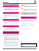
Introduction Heater Warnings Warning To Installer • Correct installation of this heater is necessary to ensure safe and proper operation. Read and understand this manual before attempting to install the heater. Failure to follow all these instructions could cause serious or fatal injury. Warning - Explosion Hazard • Heater must be turned off while re-fueling. • Do not install heater in enclosed areas where combustible fumes may be present.
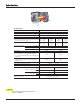
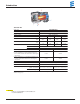
Introduction Technical data HYDRONIC M-II Heater type Heater HYDRONIC M8 Biodiesel Version D8W Heating medium Water, Cooling fluid Control of the heat flow Power High Medium Low 17061 5000 11943 3500 5118 1500 0.24 0.90 0.17 0.65 0.11 0.40 0.05 0.18 55 46 39 35 Heat flow (BTU) (Watt) BTU 27297 Watt 8000 Fuel consumption (g / h) (l/h) g/h l/h Figures for operation with diesel fuel. If operated with Biodiesel the heat flow can reduce by up to 15 %.
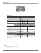
Introduction Technical data Heater type HYDRONIC M-II Heater HYDRONIC M10 Version D 10 W Heating medium Water, Cooling fluid Control of the heat flow Power High Medium Low Heat flow BTU Watt 32415 9500 27297 8000 11943 3500 5118 1500 Fuel consumption (g/h) (l/h) 0.32 1.2 0.24 0.9 0.11 0.4 0.05 0.18 86 60 39 35 Electrical power (Watt) in operation at start – after 25 Sec.
Introduction Technical data Heater type HYDRONIC M-II Heater HYDRONIC M12 Version D 12 W Heating medium Water, Cooling fluid Control of the heat flow Power High Heat flow BTU 42000 32415 17061 11943 5118 4095 Fuel consumption (g/h) (l/h) .40 1.5 .32 1.2 .17 0.65 .11 0.40 .05 0.18 .04 0.15 132 86 46 39 35 34 in operation Electrical power (Watt) Medium 1 Medium 2 Medium 3 at start – after 25 Sec.
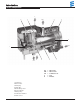
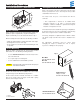
Introduction Heater Components F 2 3 4 WO 5 6 WI 1 E 9 8 7 CA WI WO CA F E = = = = = Water inlet Water outlet Combustion air Fuel Exhaust 1 Control box 2 Burner motor 3 Glow plug 4 Flame pipe 5 Overheating sensor 6 Heat exchanger 7 Water pump 8 Combustion chamber 9 Flame sensor 7
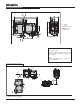
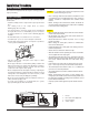
Introduction Principal Dimensions F WO M8 (x4) E Exhaust F Fuel CA Combustion air WO Water outlet WI Water inlet WI CA E * All measurements in millimeters 25.4 mm = 1” Boxed Heaters Insure: Minimum installation distance (clearance) to open the lid and to dismount the glow pin and the control unit. Insure: Minimum installation distance (clearance) to take in combustion air.
Installation Procedures Principal Dimensions - Boxed Version Arrangement of the heater Parts of the structure and other components near the heater must be protected from excess heat exposure and possible contamination from fuel or oil. 317 mm (12.4”) 430 mm (16.9”) 197 mm (7.76”) Heater Location Always mount the heater in a protected area. Eg: storage compartment, engine compartments, step box or battery box. Espar recommends you use the boxed unit. Refer to fig.
Installation Procedures Heater Plumbing The heater is incorporated into the engine’s cooling system for engine preheating. Engine Plumbing Follow these guidelines and refer to the engine plumbing diagram shown below. • Install hose fittings into the engine block for pick-up and return lines. • Use existing holes in the engine block (ie. remove blanking plugs when possible). • Use shut off valves to ensure the system can be isolated from the engine when not in use.
Installation Procedures Caution: The coolant must contain a minimum of 10% antifreeze at all times as protection against corrosion. Fresh water will corrode internal heater parts. • The exhaust outlet must end in the open air. • The exhaust pipe must not protrude beyond the lateral limits of the vehicle. • Install the exhaust pipe sloping slightly downwards. If necessary, make a drain hole approx. Ø 5 mm at the lowest point to drain off condensation.
Installation Procedures Fuel System Fuel Line • Route fuel lines from the fuel pick-up pipe to the heater. The Hydronic MII boxed unit is most commonly provided with the fuel metering pump mounted inside the box. This is to reduce installation time and to protect the pump from corrosion. If specifications cannot be met the pump must be mounted externally. See illustration for connections and specifications. All parts necessary to do the installation are included in the kit as shown.
Installation Procedures Fuel Metering Pump Installation If the pump needs to be mounted externally follow these guidelines: • Choose a protected mounting location close to the fuel pickup pipe and heater. 15° to vertical • Using the bracket and rubber mount provided, install pump as shown. 15° Note: Proper mounting angle of the pump is necessary to allow any air or vapor in the fuel lines to pass through the pump rather than cause a blockage.
Installation Procedures Electrical Connections Caution: To avoid potential short circuit damage during instal lation, insert main fuse into the power harness after all electrical connections are complete. A) Power Harness................................................................... Note: Wire must be inserted into fuse holder prior to terminating. Note: All harnesses should be cut to length. All exposed electrical connections should be coated with protective grease. • 2 core harness (red, brown).
Installation Procedures Exhaust Connection Intake Connection A 30 mm flexible tube exhaust pipe with a length of 1M long is supplied with the kit for the exhaust. An exhaust clamp is needed to secure the exhaust to the the heater. The exhaust hose cannot be any longer than 2 m. Connect the exhaust as follows: • Connect the exhaust pipe to the exhaust port on the heater and attach with clamp provided. Feed the exhaust pipe through the silicone (white) grommet on the bottom of the box.
Installation Procedures Operating Switches A 7 Day Timer , a Push/Pull switch or an easy start timer are available for the heater. a4) a3) a5) a2) Yellow Blue RESET AUTO MANUA L CLOCK TIMER DAY HOUR MIN Red Brown MANUAL 12 11 10 9 8 7 6 5 4 3 2 1 Option #1 Red Yellow Brown Blue TRS DIAG P Option #2 7 Day Timer Instructions The 7 Day Timer has been designed to provide a simple means to control the operation of the heater system and to include the capability for diagnostics.
Installation Procedures Using the Heater Manually with the Vehicle Accesory “On” (Optional wire on pin 10 is connected to the ignition lock) Push buton. The symbol will appear in the display next to the time of day. The time of day will remain displayed during ignition on operation. The heater will function continually as long as the vehicle ignition is “On”. When the vehicle ignition is turned “Off” the heater will continue to operate for an additional 15 minutes.
Installation Procedures Push/Pull Switch • Mount switch in a location where it is easily accessible Setting the time • Mount using hardware supplied Press and hold the CLOCK button. Press DAY button to select the correct day. Press HOUR button to select the correct hour. Press MIN button to select the correct minutes. When the MIN button is released the time will be set.
Notes: 19
Heater Operation Pre-Start Procedures Upon completion of installation prepare the heater as follows: • Check all fuel, electrical and plumbing connections. • Refill the engine coolant. • Bleed air from the coolant system by running the engine and refilling the antifreeze as needed. Resecure heater hose. • Run engine to further bleed the system • Top up engine coolant.
Heater Operation Heater Wiring The heater is to be connected up electrically according to the EMC directives. 12-pin Connection Pin Assignment Connector is shown from the lead entry side. Caution: EMC can be affected if the heater is not connected up correctly. For this reason, comply with the following instructions: • Cable harness HYDRONIC M Ensure that the insulation of electrical cables is not damaged. Avoid: chafing, kinking, jamming or exposure to heat.
Heater Operation Parts list for wiring diagram, Hydronic M-II - 12 Volt / 24 Volt 1.1 1.2 1.2.1 1.5 1.12 1.13 Blower motor Glow pin I Glow pin II (optional 12 kW) Overheating sensor Flame sensor Temperature sensor 2.1 2.2 2.5.7 2.5.18 2.7.1 2.7.5 2.12 Control unit Fuel metering pump Relay, vehicle blower (fan) Relay, changeover water circuit (To be fitted by customer if required) Main fuse 12 volt = 20A 24 volt = 15A Fuse, control option 5A Fuse, vehicle blower (fan) 25A Water pump 5.1 5.
Heater Operation Hydronic M-II, Wiring Diagram - 12 Volt / 24 Volt Circuit diagram HYDRONIC M-II – 12 Volt / 24 Volt B3 S3 x) Optional 5.10 Black/Violet Black Red Brown Brown / Green Brown b) b) Brown Brown Red Red Red Yellow C4 B3 9 C3 B4 6 3 2.7 2.7.5 2.7.1 B2 C2 B1 5 C1 A4 8 B2 Blue / White A3 Green Brown Red White / Red A2 A1 Red / Yellow c) S2 a) White/Red Blue/White Yellow Red Brown a1) a2) a3) a4) a5) Brown B3 2.5.18 Red / Yellow 2.5.7 2.2 5.1 2.
Heater Operation Hydronic M-II, Controler Options Push/Pull switch RED a4) YELLOW a3) 0 0 BROWN a5) 15 (K) K (15) 31 Push / Pull Switch a4) a3) a5) a2) Red Yellow Brown Blue 12 11 10 9 8 7 6 5 4 3 2 1 Option #1 Yellow Blue Red Brown TRS DIAG P 7 Day Timer Option #2 Programmable Timer a3) Yellow (Signal to Heater) 5 4 a5) a4) 5670100 - 12 Volt 5670099 - 24 Volt 3 2 Brown (-) Red (+) RESET Programmable Timer 1 AUTO MANUA L CLOCK TIMER DAY HOUR MIN MANUAL Programmable T
Maintenance, Troubleshooting & Repairs PeriodicRight Maintenance Subtitle Page Fault Code Retrieval Device • Check coolant hoses, clamps, and make sure all valves are open. Maintain the engine manufacturers recommended coolant level and ensure that the heater is properly bled after service on or involving the coolant system. Equipment Face and Controls • Visual check of all fuel lines for leaks. Check and if necessary replace fuel filter inserts.
Maintenance, Troubleshooting & Repairs Fault Code Fault Description Causes / Repair ——— Diagnosis not possible • Adapter cable not connected properly. • Diagnostic connection damaged. • Internal control box fault, replace control box / blower unit. 000 No faults —— 005 Warning Short circuit in "Burglar Alarm" output • Check connection and / or lead for continuity, short circuit and damage.
Maintenance, Troubleshooting & Repairs Fault Code Fault Description 020 Glow plug 1, interruption 021 Glow plug 1, overload / short circuit downstream of (–) Glow plug 1, short circuit downstream of (+) 022 Causes / Repair • Measure cold resistance of the glow plug at approx. 20°C ambient temperature – connector B1, PIN 7 and 10. If the values are as follows the glow plug is ok, if the values differ – replace the glow plug. Measured value: • 12 volt – glow plug = 0.42 – 0.
Maintenance, Troubleshooting & Repairs Fault Code Fault Description Causes / Repair 047 Metering pump Overload short circuit • Check the metering pump's connection and lead harness for continuity, short circuit and damage – connector B2, PIN A1. – If ok, check the resistance of metering pump – setpoint value approx. 20 ohm.
Maintenance, Troubleshooting & Repairs Fault Code Fault Description Causes / Repair 071 Overheating sensor interruption Overheating sensor signals temperature value outside the measuring range. • Check overheating sensor –> fault code 012. 072 Overheating sensor short circuit 074 Overheating detection hardware is defective, operating lock-out • Control box is defective. Replace control box / blower unit. 090 External reset • Control box reset by external interference voltage.
Maintenance, Troubleshooting & Repairs Repair Instructions The permitted repair work on the heater is described in the "Repair Instructions" chapter. The heater must be removed from the vehicle for the repair work to be carried out. The heater is assembled in the reverse order, note and follow any additional instructions. Terminal Removal Tools are used to release plug-in contacts in a connector housing. Terminal Removal Tool 1.
Maintenance, Troubleshooting & Repairs Preparatory work for all repairs Figure 1 and 2 • Clamp the removed heater in a retaining device (vice). • Using 2 screwdrivers, always undo 2 snap connections of the impeller cover at a time, starting at the control box/blower unit. Keep to the order shown in the figure (1.– 8.) • Remove cover. • Remove O-ring (2). Note: The O-ring (2) must always be renewed.
Maintenance, Troubleshooting & Repairs Repair step 1 Dismantle control box/blower unit and jacket Remove water pump connector Figure 6 • Disconnect the connector (24) at the water pump (26) and pull the cable loom out of the holder. Remove side cover and dismantle jacket Figure 7 • Pull out side cover (3) from above. • Undo the 4 screws (21) M5 x 25 in the jacket (20) and remove the jacket from the control box / blower unit. Note: The control box / blower unit may not be placed on the exposed impeller.
Maintenance, Troubleshooting & Repairs Repair step 1 Dismantle control box/blower unit and jacket Disconnect 14-pin connector at control box and release cables Figure 9 – 11 / Sketch 1 • Use side cutters to open the cable tie (12). • Disconnect the 14-pin connector (29). • Use the terminal removal tool to remove pins in the 14-pin connector (29) for the electric motor, flame sensor (11), glow plug 1(5) and glow plug 2 (6). • Expose the cables of the two glow plugs from above (cable duct).
Maintenance, Troubleshooting & Repairs Repair step 1 Control box / blower unit and jacket Remove flame sensor Figure 12 • Unscrew the flame sensor (11) from the housing of the control box / blower unit. Dismantle combustion chamber Figure 13 and 14 • Undo the 3 screws (9) M5 x 16 of the combustion chamber (8). • Lift the combustion chamber (8) with the fuel pipe until the grommet (22) is exposed, then remove the combustion chamber. • Remove combustion chamber seal (23).
Maintenance, Troubleshooting & Repairs Repair step 2 Assemble the control box/blower unit and jacket Install combustion chamber seal Figure 15 and 16 • Carefully guide the combustion chamber seal (23) over the cables of the glow plugs and over the fuel pipes and position on the combustion chamber (8). Note: Take care when installing the new combustion chamber seal (23) as there is a risk of breaking it.
Maintenance, Troubleshooting & Repairs Repair step 2 Assemble the control box/blower unit and jacket Install combustion chamber Figure 19 • Use 3 screws (9) M5 x 16 to fix the combustion chamber (8). Tightening torque M5 x 16 screw. Lay sensor lead harness and leads of the glow plugs Figure 20 and 21 • First lay the sensor lead harness (19) in the side cable duct, then lay the 4 leads of glow plugs 1 (5) and 2 (6) in the cable duct.
Maintenance, Troubleshooting & Repairs Repair step 2 Assemble the control box/blower unit and jacket Install flame sensor Figure 22 • Screw the flame sensor (11) into the housing of the control box / blower unit. Flame sensor tightening torque.
Maintenance, Troubleshooting & Repairs Repair step 2 Assemble control box/blower unit and jacket Connect the glow plug leads Figure 24, 25 and Sketch 3 • First, latch the leads of glow plug 2 (6 / short leads) into position in the 14-pin connector (29). Then wind the leads of glow plug 1 (5) 2 x around the leads already latched into position in the 14-pin connector and then latch into position in the 14-pin connector (29). Use a cable tie (12) to bundle all leads above the winding.
Maintenance, Troubleshooting & Repairs Repair step 2 Assemble control box/blower unit and jacket Install electric motor cover Figure 26 and 27 • Position the electric motor cover (13) on the housing of the control box / blower unit, at the same time, insert the water pump lead harness in the groove provided in the cover. • Use 2 screws (14) M5 x 16 to fasten the electric motor cover (13) onto the housing of the control box / blower unit. .
Maintenance, Troubleshooting & Repairs Repair step 2 Control box/blower unit and jacket Lay water pump lead harness Figure 29 • Insert the water pump lead harness into the holder on the jacket, lay up to the water pump and connect. Install overheating and temperature sensor Figure 30 and 31 • Insert the overheating (17) and temperature sensor (18) into the holders on the jacket. Insert the sensor cable loom (19) into the holders on the jacket.
Maintenance, Troubleshooting & Repairs Repair step 2 Control box/blower unit and jacket Install impeller cover Figure 32 • Clamp the removed heater in a retaining device (vice) and position the new O-ring (2) on the control box / blower unit. • Install the impeller cover; ensure that none of the leads of the sensor lead harness (19) get jammed.
Maintenance, Troubleshooting & Repairs Repair step 3 Control box/blower unit and jacket Remove / check glow pin Figure 33 • Carry out repair step 1. • Unscrew glow pins 1 (5) and 2 (6) from the combustion cham ber housing (8) (See page 36), if necessary check the glow plugs; for check values see fault code 020 / 021. • Visually check the glow pin socket lining, if necessary renew the glow pin lining.
Maintenance, Troubleshooting & Repairs Repair step 4 Remove glow pin socket lining Figure 35 • Carry out repair step 1. • Unscrew glow pin from the combustion chamber housing (8). • Use a pointed object to pull the glow pin socket lining out of the glow pin socket. Install glow pin socket lining Figure 36, 36/1 • Insert the glow pin socket linings, with the bevelled edge facing upwards, into the spark plug sockets up to the limit stop.
Maintenance, Troubleshooting & Repairs Repair step 5 Check overheating and temperature sensor Figure 37 / Diagram 1 • Removal of the overheating (17) and temperature sensor (18) is described in repair step 1. • Use the digital multimeter to check the overheating (17) and temperature sensor (18). If the resistance value lies outside the table of values or the diagram, then replace the overheating (17) and temperature sensor (18).
Maintenance, Troubleshooting & Repairs Repair step 6 Check flame sensor Figure 38 / Diagram 2 • Removal of the flame sensor (11) is described in repair step 1. • Use the digital multimeter to check the flame sensor (11). If the resistance value lies outside the table of values or the diagram, then replace the flame sensor (11). • Installation of the flame sensor (11) is described in repair step 2.
Maintenance, Troubleshooting & Repairs Repair step 7 Remove / attach water pump Figure 39 • Disconnect the connector (24) at the water pump (26). • Undo the hose clip (25) • Remove the water pump. • Check O-ring (See page 50 parts diagram #13), replace if necessary • Install in the reverse order. Note: When assembling the O-ring coat it with lubricant.
Maintenance, Troubleshooting & Repairs Measuring the fuel quantity Preparing for the measurement Evaluation (Sketch 4) Compare the measured quantity of fuel with the values in the following table. • Disconnect the fuel pressure line at the heater and place the end in a measuring cylinder (size 25 ml). If the measured quantity of fuel is above the maximum value or below the minimum value, the metering pump must be replaced.
Heater Components Hydronic M-II Parts Diagram 48
1 Combustion air blower/ECU 12 V 25 2470 99 15 00 24 V 25 2471 99 15 00 12 V 25 2434 99 15 00 24 V 25 2435 99 15 00 12 V 25 2472 99 15 00 24 V 25 2473 99 15 00 24V 12V 24V 12V 24V 25 2434 05 25 2435 05 25 2472 05 25 2473 05 Part Number 25 2471 05 Ref. No.
Heater Components Subtitle Left Page Diagram Hydronic M Parts 34 2e 32 31 2c 2b 33 2d 50
1 Fuel metering pump 24V 12V 24V 12V 24V 25 2434 05 25 2435 05 25 2472 05 25 2473 05 Part Number 25 2471 05 Ref. No.
Heater Components 12V 24V 12V 24V 12V 24V 25 2471 05 25 2434 05 25 2435 05 25 2472 05 25 2473 05 31 Fuse 25 A 15 A 5A 204 00 089 204 00 003 204 00 079 • • • • • • • • • • • • • • • • • • 32 Relay 12 V 24 V 203 00 065 203 00 066 • 20 2900 70 90 16 20 2900 70 90 08 20 2900 70 90 13 5670380 20 2900 70 90 14 • • • • • • • • • • 890 31 101 • • 5670196 • • Description & Part #’s Ref. No.
1st Printing - Apr 2008 Printed in Canada P/N: 20 2900 81 0102 0A Espar Products, Inc. (800) 387-4800 (905) 670-0960 www.espar.