
Operating instructions
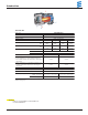

10
I
I
n
n
s
s
t
t
a
a
l
l
l
l
a
a
t
t
i
i
o
o
n
n
P
P
r
r
o
o
c
c
e
e
d
d
u
u
r
r
e
e
s
s
Heater Plumbing
42
3
1
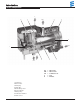
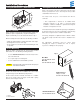
The heater is incorporated into the engine’s cooling system for
engine preheating.
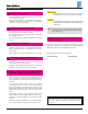
Follow these guidelines and refer to the engine plumbing diagram
shown below.
• Install hose fittings into the engine block for pick-up and return
lines.
• Use existing holes in the engine block (ie. remove
blanking plugs when possible).
• Use shut off valves to ensure the system can be isolated from
the engine when not in use. Alternatively “T” piece connectors
in existing coolant hoses can be used if no blanking plugs are
available.
• Provide 20mm (3/4” ) hose barbs for hose connections.
• Use 20mm (3/4” ) hoses to ensure adequate coolant flow.
• Keep the pick up and return points as far apart as possible to
ensure good heat distribution.
• Take the coolant from a low point on the engine to reduce
aeration in the system.
• Ensure proper direction of coolant flow by taking coolant from a
high pressure point in the engine and returning it to a low pres-
sure point. (ie. pickup from back of block and return to the
suction side of the engine's water pump).
• Ensure adequate flow rate through the heater by comparing the
incoming and outgoing coolant temperatures while the heater is
running. If the rise in temperature exceeds 10°C (18°F), coolant
flow must be increased by modifying the plumbing.
• Ensure the heater and water pump are installed as low as pos
sible to allow the purging of air.
• If a bunk heat exchanger is incorporated into the system,
proper plumbing layouts must be followed.
Water in
Water out
Engine Plumbing
Caution: It is possible for the coolant and components of the
coolant circuit to get very hot.
• Parts conveying water must be routed and fastened in such
a way that they pose no temperature risk to man, animals or
material sensitive to temperature from radiation / direct
contact.
• Before working on the coolant circuit, switch the heater off
and wait until all components have cooled down completely,
if necessary where safety gloves.
Caution:
• When installing the heater, please take note of the direction
of flo
w of the coolant circuit.
• Fill the heater and water hoses with coolant before con-
necting to the coolant circuit.
• Route the water hoses without any kinks, and in a rising
position if possible.
• When routing the water pipes, observe a sufficient clea-
rance to hot vehicle parts.
• Protect all water hoses / water pipes from chafing and from
extreme temperatures.
• Secure all hose connections with hose clips.
• After the vehicle has been operating for 2 hours or travelled
100 km, tighten the hose clips again.
• The minimum water flow rate is only guaranteed if the tem
perature difference of the heating medium does not exceed
15°C
(60°C)
between water inlet and water outlet during
heating.
• Only overpressure valves with an opening pressure of min.
6 psi – max. 30 psi bar may be used in the coolant circuit.
• The coolant liquid must contain at least 10 % antifreeze all
year round as corrosion protection.
• The cooling liquid must contain sufficient antifreeze for low
temperatures.
• Before commissioning the heater or after changing the
cooling liquid, the whole coolant circuit including heater must
be vented free of bubbles according to the instructions issued
by the vehicle manufacturer.
• Only top up with coolant approved by the vehicle manufac-
turer.
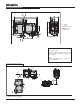
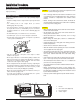
1 Heater
2 Non-return valve (Optional)
3 Heat exchanger
4 Vehicle engine