
User's Manual

2. Getting Started
Result
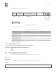
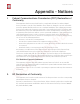
The flash layout is shown as Figure 2-3.
For the flash usage, refer to Table 2-5.
2.1.5.
Running Application
1.
Power off and switch the hardware to the running mode.
2.
Power on the hardware and run the application.
🔚
2.2.
SSC Command Reference
Here lists some common Wi-Fi commands for you to test the board.
2.2.1.
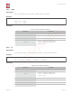
op
Description
op commands are used to set and query the Wi-Fi mode of the system.
Example
op -Q
Figure 2-3. Flash Layout
16K
boot.bin
240K
irom1.bin irom0_flash.bin
3840K
esp_init_data_default.bin
4K 4K 4K
blank.bin
System Parameter
Available segment
4K
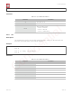
Table 2-5. Flash Usage
Segment Name
Start Address
Length
dport0_0_seg
org = 0x3FF00000
len = 0x10
dram0_0_seg
org = 0x3FFD8000
len = 0x24000
iram1_0_seg
org = 0x40040000
len = 0x20000
irom0_0_seg
org = 0x40080010
len = 0x37FFF0
irom0_1_seg
org = 0x3FE04010
len = 0x3BFF0
Espressif
2015.12
Confidential