
User's Manual

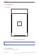
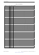
Table Of Contents
2. Pin Definitions
2. Pin Definitions
2.1 Pin Layout
PCB Antenna
GND
EN
IO46
IO45
RXD0
TXD0
IO42
IO41
IO40
IO39
IO38
IO37
IO36
IO35
IO34
IO33
1
2
3
4
5
6
7
8
9
10
11
12
13
14
15
16
42
41
40
39
38
37
36
35
34
33
32
31
30
29
28
27
GND
3V3
IO0
IO1
IO2
IO3
IO4
IO5
IO6
IO7
IO8
IO9
IO10
IO11
IO12
IO13
43 GND
17
18
19
IO14
IO15
IO16
20
21
22
IO17
IO18
IO19
23
24
25
IO20
IO21
IO26
26 GND
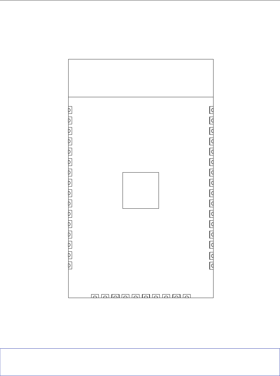
Figure 1: Module Pin Layout (Top View)
Note:
The pin diagram shows the approximate location of pins on the module. For the actual mechanical diagram, please refer
to Figure 7.1 Physical Dimensions.
2.2 Pin Description
The module has 42 pins. See pin definitions in Table 2.
Espressif Systems
4
Submit Documentation Feedback
ESP32-S2-WROOM & ESP32-S2-WROOM-I User Manual V0.5