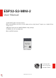
ESP32-S2-MINI-2 User Manual 2.4 GHz Wi-Fi (802.11 b/g/n) module Built around ESP32-S2 series of SoC (chip revision v1.0), Xtensa® single-core 32-bit LX7 microprocessor 4 MB flash and optional 2 MB PSRAM in chip package 37 GPIOs, rich set of peripherals On-board PCB antenna ESP32-S2-MINI-2 Pre-release v0.5 Espressif Systems Copyright © 2022 www.espressif.
1 Module Overview 1 Module Overview ESP32-S2-MINI-2 is a general-purpose Wi-Fi module. The rich set of peripherals and a small size make this module an ideal choice for smart homes, industrial automation, health care, consumer electronics, etc. Table 1: ESP32-S2-MINI-2 Specifications Categories Wi-Fi Parameters Specifications Protocols 802.
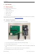
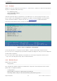
Contents Contents 1 Module Overview 2 2 Pin Definitions 4 2.1 Pin Layout 4 2.2 Pin Description 4 3 Get Started 7 3.1 What You Need 7 3.2 Hardware Connection 7 3.3 Set up Development Environment 8 3.3.1 Install Prerequisites 8 3.3.2 Get ESP-IDF 8 3.3.3 Set up Tools 9 3.3.4 Set up Environment Variables 9 3.4 Create Your First Project 9 3.4.1 Start a Project 9 3.4.2 Connect Your Device 3.4.3 Configure 10 3.4.4 Build the Project 10 3.4.
2 Pin Definitions 2 Pin Definitions 2.1 Pin Layout The pin diagram below shows the approximate location of pins on the module.
2 Pin Definitions Table 2 – cont’d from previous page Name 1 No.
2 Pin Definitions 1 P: power supply; I: input; O: output; T: high impedance. 2 IO26 is used by the embedded PSRAM on the ESP32-S2-MINI-2-N4R2 module, and cannot be used for other purposes. Espressif Systems 6 ESP32-S2-MINI-2 User Manual v0.
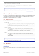
3 Get Started 3 Get Started 3.1 What You Need To develop applications for module you need: • 1 x ESP32-S2-MINI-2 • 1 x Espressif RF testing board • 1 x USB-to-Serial board • 1 x Micro-USB cable • 1 x PC running Linux In this user guide, we take Linux operating system as an example. For more information about the configuration on Windows and macOS, please refer to ESP-IDF Programming Guide. 3.2 Hardware Connection 1. Solder the ESP32-S2-MINI-2 module to the RF testing board as shown in Figure 2.
3 Get Started 7. After download, remove the jumper on IO0 and GND. 8. Power up the RF testing board again. The module will switch to working mode. The chip will read programs from flash upon initialization. Note: IO0 is internally logic high. If IO0 is set to pull-up, the Boot mode is selected. If this pin is pull-down or left floating, the Download mode is selected. For more information on ESP32-S2-MINI-2, please refer to ESP32-S2 Series Datasheet. 3.
3 Get Started 1 mkdir -p ~/esp 2 cd ~/esp 3 git clone --recursive https://github.com/espressif/esp-idf.git ESP-IDF will be downloaded into ~/esp/esp-idf. Consult ESP-IDF Versions for information about which ESP-IDF version to use in a given situation. 3.3.3 Set up Tools Aside from the ESP-IDF, you also need to install the tools used by ESP-IDF, such as the compiler, debugger, Python packages, etc. ESP-IDF provides a script named ’install.sh’ to help set up the tools in one go.
3 Get Started 3.4.3 Configure Navigate to your ‘hello_world’ directory from Step 3.4.1. Start a Project, set ESP32-S2 chip as the target and run the project configuration utility ‘menuconfig’. 1 cd ~/esp/hello_world 2 idf.py set-target esp32s2 3 idf.py menuconfig Setting the target with ‘idf.py set-target ESP32-S2’ should be done once, after opening a new project. If the project contains some existing builds and configuration, they will be cleared and initialized.
3 Get Started 4 Warn about uninitialized values. 5 -- Found Git: /usr/bin/git (found version ”2.17.0”) 6 -- Building empty aws_iot component due to configuration 7 -- Component names: ... 8 -- Component paths: ... 9 10 ... (more lines of build system output) 11 12 [527/527] Generating hello_world.bin 13 esptool.py v2.3.1 14 15 Project build complete. To flash, run this command: 16 ../../../components/esptool_py/esptool/esptool.
3 Get Started 14 Stub running... 15 Changing baud rate to 460800 16 Changed. 17 Configuring flash size... 18 Flash will be erased from 0x00000000 to 0x00004fff... 19 Flash will be erased from 0x00010000 to 0x00039fff... 20 Flash will be erased from 0x00008000 to 0x00008fff... 21 Compressed 18896 bytes to 11758... 22 Writing at 0x00000000... (100 %) 23 Wrote 18896 bytes (11758 compressed) at 0x00000000 in 0.5 seconds (effective 279.9 kbit/s) 24 Hash of data verified.
3 Get Started 11 ... After startup and diagnostic logs scroll up, you should see “Hello world!” printed out by the application. 1 ... 2 Hello world! 3 Restarting in 10 seconds... 4 This is esp32s2 chip with 1 CPU core, WiFi, 5 silicon revision 1 6 Minimum free heap size: 390684 bytes 7 Restarting in 9 seconds... 8 Restarting in 8 seconds... 9 Restarting in 7 seconds... To exit IDF monitor use the shortcut Ctrl+].
4 U.S. FCC Statement 4 U.S. FCC Statement The device complies with KDB 996369 D03 OEM Manual v01. Below are integration instructions for host product manufacturers according to the KDB 996369 D03 OEM Manual v01. List of Applicable FCC Rules FCC Part 15 Subpart C 15.247 Specific Operational Use Conditions The module has WiFi functions. • Operation Frequency: – WiFi: 2412 ~ 2462 MHz • Number of Channel: – WiFi: 11 • Modulation: – WiFi: DSSS; OFDM • Type: On-board PCB antenna • Gain: 4.
4 U.S. FCC Statement Antennas Antenna specification are as follows: • Type: On-board PCB antenna • Gain: 4.54 dBi This device is intended only for host manufacturers under the following conditions: • The transmitter module may not be co-located with any other transmitter or antenna. • The module shall be only used with the external antenna(s) that has been originally tested and certified with this module. • The antenna must be either permanently attached or employ a ‘unique’ antenna coupler.
4 U.S. FCC Statement in a residential installation. This equipment generates, uses and can radiate radio frequency energy and, if not installed and used in accordance with the instructions, may cause harmful interference to radio communications. However, there is no guarantee that interference will not occur in a particular installation.
4 U.S. FCC Statement End Product Labeling The final end product must be labeled in a visible area with the following: “Contains Transmitter Module FCC ID: 2AC7Z-ESPS2MINI2”. Espressif Systems 17 ESP32-S2-MINI-2 User Manual v0.
5 Related Documentation and Resources 5 Related Documentation and Resources Related Documentation • ESP32-S2 Series Datasheet – Specifications of the ESP32-S2 hardware. • ESP32-S2 Technical Reference Manual – Detailed information on how to use the ESP32-S2 memory and peripherals. • ESP32-S2 Hardware Design Guidelines – Guidelines on how to integrate the ESP32-S2 into your hardware product. • ESP32-S2 Series SoC Errata – Descriptions of errors in ESP32-S2 series of SoCs from chip revision 0 forward.
Revision History Revision History Date Version Release notes 2022-09-22 v0.5 Preliminary release Espressif Systems 19 ESP32-S2-MINI-2 User Manual v0.
Disclaimer and Copyright Notice Information in this document, including URL references, is subject to change without notice. ALL THIRD PARTY’S INFORMATION IN THIS DOCUMENT IS PROVIDED AS IS WITH NO WARRANTIES TO ITS AUTHENTICITY AND ACCURACY. NO WARRANTY IS PROVIDED TO THIS DOCUMENT FOR ITS MERCHANTABILITY, NONINFRINGEMENT, FITNESS FOR ANY PARTICULAR PURPOSE, NOR DOES ANY WARRANTY OTHERWISE ARISING OUT OF ANY PROPOSAL, SPECIFICATION OR SAMPLE.