
User Manual

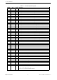
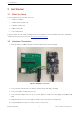
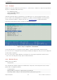
Table Of Contents

2 Pin Definitions
2 Pin Definitions
2.1 Pin Layout
The pin diagram below shows the approximate location of pins on the module.
Pin 1
Pin 2
Pin 3
Pin 4
Pin 5
Pin 6
Pin 7
Pin 8
Pin 9
Pin 10
Pin 11
Pin 12
Pin 13
Pin 14
Pin 15
GND
GND
3V3
IO0
IO1
IO2
IO3
IO4
IO5
IO6
IO7
IO8
IO9
IO10
IO11
Pin 63
GND
IO12
Pin 16
Pin 17
Pin 18
Pin 19
Pin 20
Pin 21
Pin 22
Pin 23
Pin 24
Pin 25
Pin 26
Pin 27
Pin 28
Pin 29
Pin 30
Pin 64
GND
Pin 31
IO13
IO14
IO15
IO16
IO17
IO18
IO19
IO20
IO21
IO26
NC
IO33
IO34
GND
Pin 32
Pin 33
Pin 34
Pin 35
Pin 36
Pin 37
Pin 38
Pin 39
Pin 40
Pin 41
Pin 42
Pin 43
Pin 44
Pin 45
Pin 65
GND
Pin 62
GND
Pin 46
Pin 47
Pin 48
Pin 49
Pin 50
Pin 51
Pin 52
Pin 53
Pin 54
Pin 55
Pin 56
Pin 57
Pin 58
Pin 59
Pin 60
Pin 61
GND
GND GND GND
GNDGND
GND GND GND
IO35
IO36
IO37
IO38
IO39
IO40
IO41
IO42
TXD0
RXD0
IO45
GND
GND
IO46
EN
GND
GND
GND
GND
GND
GND
GND
GND
GND
GND
GND
GND
GND
GND
GND
Keepout Zone
Figure 1: Pin Layout (Top View)
2.2 Pin Description
The module has 65 pins. See pin definitions in Table 2.
For peripheral pin configurations, please refer to
ESP32-S2 Series Datasheet.
Table 2: Pin Definitions
Name No. Type
1
Function
GND
1, 2, 30,
42, 43,
46-65
P Ground
3V3 3 P Power supply
Cont’d on next page
Espressif Systems 4 ESP32-S2-MINI-2 User Manual v0.5