ESSE 1 Smoke Exempt Wood Burning Stove INSTALLATION & USER INSTRUCTIONS (TO BE LEFT WITH THE CUSTOMER) GB IE
CONTENTS General Safety Notes Installation instructions Chimney & Flue Flue Draught Flue Stabiliser Dimensions & Clearances Installing the Stove Page 2 Page 3 Page 4 Page 6 Page 7 Page 7 Page 9 Commissioning Checklist Operating Instructions Wood Burning Solid Fuel Burning Technical Information Maintenance Guarantee Page 13 Page 15 Page 16 Page 20 Page 23 Page 25 Page 26 GENERAL SAFETY NOTES Properly installed, operated and maintained, this appliance will not emit fumes into the dwellin
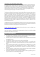
CLEAN AIR ACT 1993 AND SMOKE CONTROL AREAS Under the Clean Air Act local authorities may declare the whole or part of the district of the authority to be a smoke control area. It is an offence to emit smoke from a chimney of a building, from a furnace or from any fixed boiler if located in a designated smoke control area.
It is essential that the fire has adequate air supply for combustion and ventilation. Apertures provided for this purpose shall not be restricted. CO Alarms Building regulations require that whenever a new or replacement fixed solid fuel or wood/biomass appliance is installed in a dwelling, a carbon monoxide (CO) alarm must be fitted in the same room as the appliance, in accordance with BS EN 50292:2002.
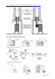
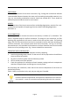
Fig.1 – Ideal Flue Connections (Flue box available from www.esse.com) Fig.
FLUE DRAUGHT The chimney can be checked, before the stove is installed, with a smoke match. If the chimney doesn't pull the smoke it may suggest the chimney needs attention (see the Flue Diagnosis Table, below). This test is only a guide as an apparently poor flue may improve once the stove is installed, lit and the flue is warmed. If, once the stove is installed, there is any doubt that the chimney is providing an adequate draught; a flue draught reading can be taken with the stove lit.
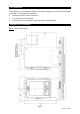
FLUE STABILISER A flue stabiliser can be fitted to reduce the draught through the stove if the flue draught is too high. The flue stabiliser should be: Fitted in the same room as the stove. The same size as the flue pipe. Fitted no closer than 700mm to the flue outlet of the appliance. DIMENSIONS & CLEARANCES Fig.
Fig.
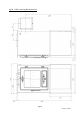
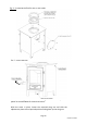
INSTALLING THE STOVE POSITIONING The overall dimensions of the stove are shown in Fig. 3 along with a table that indicates recommended distances between the stove and surrounding combustible materials. As a rule, any surrounding combustible material should not exceed 80°C. There should be sufficient space around the stove for service work. HEARTH The construction of the hearth must conform to Building Regulations, must be firm, noncombustible and capable of supporting the stove.
Fig. 4 – Arranging the flue for top or rear outlet. Fig. 5 – Stove features When positioning the stove the two rear legs are fitted with adjustment plates to accommodate for hearth variations. With the stove in place, loosen the required wing nut and slide the adjustment plate to the required position and tighten up the wing nut.
INSTALLING THE ADDITIONAL REAR HEAT SHEILD The additional heat shield kit (Part No: FM5-048) should be fitted to the stove prior to connecting the flue pipe. 1. Remove the 4 screws labelled (A). 2.
3. Fit the additional heat shield labelled (C) and fasten with the nuts provided. Remember to refit the Stove data label on the rear spacer labelled (D). Installing the optional log box 1. Remove the levelling discs from the back of the stove and fit to the back of the log box. 2. The stove can now be lifted and fitted into the slots on the top of the log box. 3. The stove can now be fitted as normal.
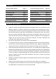
COMMISSIONING CHECKLIST To assist with any potential guarantee claim please complete the following information:To be completed by the installer.
Page 14 ONE-SE-I07-190619
OPERATING INSTRUCTIONS Over firing will damage your stove. To maintain peak efficiency, your stove should burn approximately 1.0kg of well-seasoned wood per hour. Your stove should not be used as an incinerator and only recommended fuels shall be used. Parts of the appliance, especially the external surfaces, will be hot to touch when in operation and due care will need to be taken It is essential that the fire has adequate air supply for combustion and ventilation.
RE-FUELLING ON TO A LOW FIRE BED When adding new fuel to the stove, if there is insufficient burning fuel remaining in the fire bed to light the additional fuel, you may experience excessive smoking, as the new material struggles to light. This should be avoided by using additional kindling, if required. FUEL OVERLOADING Burning excessive amounts of fuel over a sustained period can damage your stove. With this in mind, a maximum of 1kg of fuel should be added to the stove each hour.
Fig.7-Logs laid in fire box. Place a firelighter in the space and surround with a small amount of kindling. Lay a third log over the top of the space perpendicular to the other logs. Fig.8-Final log in position. When you are ready to light the fire, simply light the firelighter.
Once the fire has been lit, leave the door partially open to allow additional airflow until the fire has become established. Once the fire is established, the door should be fully closed, and the level of the primary and secondary air controllers should be carefully reduced, to achieve the desired effect When the stove is running ALL HANDLES become hot and the operating tool or glove provided should be used to open or close the door, or adjust the air controllers.
CORRECT RUNNING TEMPERATURES FOR BURNING To get the best results from your stove it is recommended that a wood stove thermometer (available from your stove dealer) be fitted to the flue pipe above the stove, at eye level if possible. The figures below show the recommended temperature of the flue gases: 115°C – 245°C The flue gases should be in this temperature band for the safest, most efficient and most economical operation of your stove.
SOLID MINERAL FUEL BURNING The Esse One-SE comes set up as a Wood Burning only stove as standard. It can be converted to burn solid mineral fuel with the purchase of the solid mineral fuel burning kit (Part No: ESSE 1 MF KIT). See instructions below to fit the conversion kit. 1 Ensure that the stove is cold and not lit. Open the door and remove all the ash, any unburnt material and the vermiculite bricks. 2 Insert both solid mineral fuel burning rear bricks (Part No: FM5-040).
6 Insert solid mineral fuel base brick (FM5047). 7 Insert the solid mineral fuel burning grate (Part No: FIREM-001). 8 Insert the remaining solid mineral fuel bottom side brick on the Right hand side of the Stove (Part No: FM5-046 &FM5-041) then fit the remaining solid mineral fuel top side brick on the right hand side of the stove (FM5-042) You may have to slide the grate to the left to slide the top brick in. 9 Re-Insert both original top baffle bricks (FM5-040T).
LIGHTING AND CONTROLLING THE FIRE Before lighting the fire for the first time, ensure that the baffle, the riddling grate and the side and back bricks are in position. Burning without either will result in the stove castings overheating and being damaged. Open the primary and secondary air control fully. Place some tightly rolled paper on top of some crumpled paper on the base towards the back of the stove.
The above text should be used as a guide only. The ideal operation of your stove depends on a number of factors, which vary with each installation, and so gaining experience operating your stove is the only way to learn its best operation. The stove as with any other metal products will expand and contract. A ticking noise may occur. This is normal for this type of appliance.
Page 24 ONE-SE-I07-190619
MAINTENANCE CLEANING THE STOVE The stove should only be cleaned when it is cold. The exterior can be dusted with a firm brush. Do not use a cloth, as this will drag on the paint finish leaving lint on the surface. From time to time it may be necessary to renovate the exterior by repainting. High temperature stove paints in aerosol form are available from your stove dealer. Do not use this form of paint until the stove is cold and always read the instructions on the container before starting to paint.
GUARANTEE CONDITIONS OF GUARANTEE Your ESSE is guaranteed against defects arising from faulty manufacture for 2 years when supplied by an ESSE Specialist. Upon registration of the warranty, ESSE will extend the guarantee period to 5 years from purchase. Your details must be registered with us by either returning the completed warranty card or by completing registration on-line at www.esse.com. The warranty must be registered within 1 month of installation to qualify for the 5 year warranty.
SPARE PARTS Only genuine ESSE spare parts are recommended. Parts that may need occasional replacement are: Fig.
Fig.
Fig.
Page 30 ONE-SE-I07-190619
Page 31 ONE-SE-I07-190619
ESSE Engineering Limited. Ouzledale Foundry, Long Ing, Barnoldswick, Lancashire, BB18 6BJ Tel: 01282 813 235, Fax: 01282 816 876 Web: www.esse.