
User Guide


6
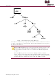
Fig
u
2
2.1
u
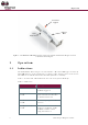
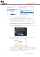
re 2: ES7
0
Ope
Indi
c
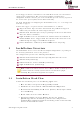
The ES
7
This LE
D
The LE
D
Table 1
Table 1
:
LED
OFF
Glows
secon
d
Glows
secon
d
Glows
secon
d
Ma
g
0
0MGLS-G
N
ratio
n
c
ation
s
7
00MGLS s
m
D
indicates
D
can be di
s
describes
t
:
LED state
red for 1
d
red for 2
d
s
green for
1
d
Smart
g
net Sensor
N
Multi-Pur
and
P
n
s
m
art magn
to the ho
m
s
abled fro
m
t
he LED in
d
s
De
s
No
i
ter
m
Pro
t
inp
u
or,
v
De
v
det
e
1
Pro
t
hav
ter
m
bei
n
pose Magn
P
ermanent
et sensor i
m
eowner a
m
the ESI-
C
d
ications fo
s
cription
i
ntrusion,
v
m
inal trigg
e
t
ected loca
t
u
t terminal
v
ibration d
e
v
ice tampe
r
e
cted
t
ected loca
t
ing been o
p
m
inal conn
e
n
g disconn
e
Mu
l
LED In
Trig
g
etic Switch
Magnet
ncludes a
b
change to
t
C
MS (defau
r each sta
t
v
ibration o
r
e
red
t
ion opene
d
disconnec
t
e
tected
r
ing has be
e
t
ion closed
p
ened, inp
u
e
cted after
e
cted
ti-Purpose
M
d
icator
g
ere
d
A
lig
n
M
with Sma
r
b
i-colored
L
t
he normal
l
t is enable
e (when e
n
d
,
t
ed
e
n
after
u
t
O
M
agnetic S
w
n
ment
M
arks
r
t Magnet
S
L
ED (green
status of
t
e
d).
n
abled):
O
peratio
n
itch
S
ensor
and red).
t
he device.
n