™ WeR@Home System User Guide ESUG05022 Version 3.
Legal Notice Usage of this document, and all information (including product information) provided within, are subject to the following terms and conditions, and all applicable laws. If you do not agree with these terms, please do not access or use the remainder of this document. This document contains highly confidential information, which is proprietary to Essence Security International (E.S.I.) Ltd. and/or its affiliates (hereafter, "Essence").
Table of Contents How to Use this Guide The backbone of this guide is the WeR@Home™ installation procedure – following an introduction to the system concept, the guide takes you through the steps of identifying the system components and their functions, preparations, and installation of the system components (hardware and software) in the recommended sequence ensuring smooth buildup of your WeR@Home™ system.
Table of Contents This page was intentionally left blank 4 WeR@Home™ System User Guide
Table of Contents Table of Contents 1. 2. 3. Introduction ..................................................................................................................................................................... 13 1.1. Foreword............................................................................................................................................................... 13 1.2. General Guidelines..................................................................................
Table of Contents 3.3.4 3.3.5 3.3.6 3.4. 3.5. 3.6. 3.7. 6 The Tool Bar...................................................................................................................................... 46 The Status/Activation Bar .............................................................................................................. 48 The Data Window ............................................................................................................................ 49 3.3.6.
Table of Contents 3.7.2.3 Installing with Pre-attached Double-side Tape .................................................. 102 3.7.2.4 Dismounting the Motion Detector ....................................................................... 102 3.7.3 Adding the Motion Detector to the WeR@Home™ System ................................................. 103 3.7.4 The Motion Detector Operational Modes ...............................................................................108 3.7.4.1 The Walk Test Mode ...
Table of Contents 4. 8 3.11.2.2 Installing the Flood Detector Transmitter Unit with Screws............................ 145 3.11.2.3 Installing the Flood Detector Sensor Unit with Screws..................................... 146 3.11.2.4 Installing Transmitter Unit with Pre-attached Double-side Tape ................... 146 3.11.2.5 Installing Sensor Unit with Pre-attached Double-side Tape............................ 146 3.11.2.6 Dismounting the Flood Detector ...............................................
Table of Contents 5. 4.1.1.2 Day Arm ....................................................................................................................... 195 4.1.1.3 Night Arm .................................................................................................................... 195 4.1.1.4 Disarm .......................................................................................................................... 196 4.1.1.5 Arming/Disarming with WeR@Home™ System Devices..............
Table of Contents 5.1.4.2 Removing the Old Battery ....................................................................................... 234 5.1.4.3 Installing a New Battery ............................................................................................ 234 5.1.5 Replacing the Indoor Siren (SRN) Batteries.............................................................................. 235 5.1.6 Replacing the Remote Control Unit (KF) Battery ......................................................
Table of Contents Appendix G Pairing and Bonding...................................................................................................................... 289 Motivation .................................................................................................................................................................... 289 Implementation .................................................................................................................................................
Table of Contents This page was intentionally left blank 12 WeR@Home™ System User Guide
Introduction 1. Introduction Welcome to the WeR@Home™ Smart Home System User Guide. The WeR@Home™ Smart Home system enables consumers manage different aspects of their homes such as security, safety, home automation and energy savings from anywhere and at any time using their PCs or smart device applications.
Introduction 1.2. General Guidelines Following are some general guidelines for the installation and day-by-day usage of the WeR@Home™ system: n Batteries should not be inserted into any of the system devices until a specific step in the installation process is reached. Proper order of installing the batteries ensures that the various components of the system are integrated into the system in the correct sequence.
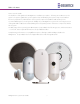
Introduction Product Central Control Unit (CCU) – Essence ES8000CP Description The WeR@Home™ Central Control Unit. Sometimes referred to as Control Panel (CP). Manage and communicate with system peripherals and the Cloud/Servers which provide the data to the different user applications. Generates notifications and source data streaming. It features: n Users’ remote access for control and management via Apple’s iOS and Google’s Android™ based smartphones/tablets and web application software.
Introduction Product Motion Detector (PIR) – Essence ES800PIR Description A Passive Infra-Red (PIR) Motion Detector peripheral device. It features: n Sealed optics, immune to light and insects for reduction of false alarms. n Multi-zone spherical lens for wide detection coverage (120o horizontal, 105o vertical). n Walk-through test mode. Door/Window Magnetic Sensor (MGL) – Essence ES800MGL Compact design magnet detector peripheral device, with long range and easy to install.
Introduction Product Power Adapter Description Universal Switching Power Supply converting the mains voltage into DC power required for the CCU. The adapter include electrical cord with mini-USB™-like connector providing the CCU with the power required for proper operation. Square Battery Pack – Essence MCBT05001 The 3.7VDC, 1400mAh Lithium Polymer rechargeable battery is the backup power source for the CCU in case of mains power shortage. Coin Battery Provides power to the Remote Control Unit (KF).
Introduction Additional devices may be purchased from local distributors as required. These are described in paragraph 1.4 and Table 2 below. 1.4. Other Available Devices The system may be expanded with accordance to the premises’ structure and protection methods, by purchasing additional components (up to the system’s limits detailed in paragraph 3.15 below).
Introduction Product Smoke Detector (SK2) – Essence ES800SK2 Description The Smoke Detector is a stand-alone fire early warning peripheral device. It features: n Tri-color LED for visual indication. n Emits loud alarm sound of 85dB from 3 m. n The Smoke Detector is fully operational even if the CCU is not. n Tamper Alarm – when detached from its base. n Long operation life. n Uses three (3) standard AA-size Alkaline batteries.
System Theory 2. System Theory The WeR@Home™ system transforms mobile smartphones and tablets, as well as personal computers (PC) into powerful remote control devices that help increase safety and enhance the quality of life of families. All system components communicate with the Central Control Unit and the CCU communicates with system servers via the cloud. The system is based on a modular structure that is flexible in its expansion capabilities – additional devices may be added to the system as needed.
System Theory 2.2. The Complete System Overview Figure 3: The WeR@Home™ Cloud Computing Network The installed system communicates via the cloud platform utilizing the following tools: n User interface software applications: ˜ Web software application running over the Internet and a PC, or ˜ Mobile software application running over GPRS/EDGE cellular network with a smartphone.
System Theory 2.3.1 Enhanced Controlled Open Protocol The WeR@Home™ products intercommunicate with the Central Control Unit (CCU) within the HAN (Home Area Network) using Essence proprietary Enhanced Controlled Open Protocol (ECOP) protocol. The WeR@Home™ CCU serves as the gateway between the HAN and the GSM/GPRS or Internet network. n Between home sensors and home control units (ECOP-R). n For external networks (control unit to the world). n ECOP-X – The XML representation of the ECOP protocol.
System Theory Sensitivity Power -103 dBm (sensors) 14 dBm -103 dBm (Central Control Unit) 20 dBm Channels, Bandwidth and Polling n Using ECOP protocol, the WeR@Home™ system utilizes between 1 to 16 channels. n The channel bandwidth is 5MHz. n The WeR@Home™ systems use Beacon-enabled network intervals, about 100ms for quick response time.
System Theory Operators can exercise full real-time control over all system functions, overview the full picture regarding customer usage, analyze usage patterns and preferences and customize services and activation for each account. The WeR@Home™ Cloud Services are based on a few fundamental building blocks, like: n Asynchronous messaging mechanism. n Control the devices’ communication layer. n Account management. n Account activation/deactivation/suspension, user preferences.
System Theory The applications are high-end Rich Internet Applications (RIA), scalable and designed for a smooth user experience while implementing push mechanisms for seamless client/server communication. 2.3.4.
System Theory This page was intentionally left blank 26 WeR@Home™ System User Guide
Installation of the WeR@Home™ System 3. Installation of the WeR@Home™ System 3.1. Prerequisites Prior to the installation and setup of the WeR@Home™ system, the following items need to be prepared: n This document is best read with Adobe Acrobat Reader® version 10.0 (or higher), available for free download at: http://get.adobe.com/reader/. An electronic format (PDF) version of this manual is available, for free download, at: http://www.essence-grp.com/pages/WeR/WeRFullUserGuide.
Installation of the WeR@Home™ System n A smartphone (optional) for remote system management. n A small screwdriver. n The Central Control Unit’s identification serial number should be registered prior to the installation process. n Stickers with the serial number can be found inside the battery/SIM-card cavity and under the Central Control Unit’s base as illustrated in Figure 4 below.
Installation of the WeR@Home™ System It is arranged in the exact same sequence the system needs to be built-up, including the steps of software installation and registration. Therefore, it is advised to follow this sequence to ensure properly functioning system. The WeR@Home™ system is based on independent components described below. The order of presenting these components is the recommended order of their installation.
Installation of the WeR@Home™ System It is a two-way, wireless Central Control Unit comprising the main element of the WeR@Home™ system. 3.2.
Installation of the WeR@Home™ System 3.2.2.1 CCU Positioning Recommendations The CCU should be installed on: n A flat surface. n In a central home/office location with: ˜ Unshielded adequate cellular coverage (if cellular communication is to be used). ˜ Close to an Internet connection outlet (modem/router connection, if Internet communication is to be used). The CCU must be activated and the system must be registered with the Service Provider (or the distributer) to enable its proper operation.
Installation of the WeR@Home™ System LED 2 LED 1 Figure 7: Insertion of LAN Cable into the CCU Socket The CCU back panel LAN (RJ45) socket provides two (2) LED status indications, active in accordance with the IEEE 802.3u standard, as a convenient means of determining the mode of operation of the network: i. LED1 (Green) is the Link Activity LED. 4. It will lit steady once the network transceiver detects a valid link and will blink upon link activity (transmit/receive). ii.
Installation of the WeR@Home™ System Figure 8: Insertion of the Backup Battery 8. Return the battery cover back to place. 9. Plug the Power Supply's cable into the mini-USB™ connector on the back of the CCU. 10. Plug the adapter’s cube into an electric power outlet socket. 11. The LED on the front panel of the Central Control Unit should light with orange color. 12. Place the CCU in its designated location. 13.
Installation of the WeR@Home™ System Note: The initial registration is a web-only procedure and therefore could be exercised utilizing the Web Application only (cannot be done with the Mobile Application). 3.2.3 Activating the Central Control Unit Notes: This paragraph details the initial registration process of the system, utilizing the WeR@Home™ Web Application software. It is a one-time procedure exercised as part of the activation of the system’s Central Control Unit.
Installation of the WeR@Home™ System 2. The Login window will pop-up: Figure 9: The WeR@Home™ Web Application Login Window Note: If prompted, install the Microsoft® Silverlight™ web application framework available for free download at: http://www.microsoft.com/getsilverlight/GetStarted/Install/Default.aspx. 14. The button allows selection of the interfacing language. 15. For the initial registration procedure no information need to be typed into the Email and Password fields.
Installation of the WeR@Home™ System Figure 10: The Login Window with the Roll-down Menu 18. Click over the _Go to first time registration page >>_ option. The First Time Registration (Step 1 of 2) window appears: Figure 11: CCU First Time Registration Window 19. Type-in the 8-digits serial number recorded on page 28 (and Appendix H) and click over the button. The Web Application software performs, at this point in time, a validation procedure to ensure the number typed is correct.
Installation of the WeR@Home™ System In case the CCU was previously incompletely registered and this procedure started before the front CCU’s LED switched to green; a Panel Not Connected error message will pop-up: Figure 12: Panel Not Connected Error Message In case this serial number was already registered with the system; an Existing Serial Number error message will pop-up: Figure 13: Existing Serial Number Error Message 20.
Installation of the WeR@Home™ System Figure 15: First Time Registration Step 2 Window Note: You may want to record the following registration details to Appendix H Owner’s Records of this guide (page 290) where important data of your system is gathered for future reference. 23. Type-in your personal details as follows: i. _Email_ – Address where system’s messages and notifications will be sent to via email. ii. This address will also be used for subsequent login (see above Figure 9). iii.
Installation of the WeR@Home™ System i. _Name_ – The User Name you will be identified with in the system. This is a case-sensitive, alphanumeric characters’ field. ii. _Enter Mobile #_ – Type-in your mobile telephone number. 25. This data is for information records only (not used at this point in time). 26. Use digits only in international telephone number format (for example: 972522728110). i.
Installation of the WeR@Home™ System Figure 16: Registration Confirmation Message Window Within a period of approximately 5 minutes, the CCU’s front LED should turn green and the registration process is concluded. Notes: If the LED remains orange (does not switch to green), it means that communication could not be established (verified and registered properly), usually due to wrong APN data. Green flashing LED means the CCU is being updated by the Remote Software Upgrade (RSU) mechanism.
Installation of the WeR@Home™ System Figure 17: APN Settings Window Most market available SIM-card’s APN data is pre-programmed into the WeR@Home™ system and being updated on a regular basis, therefore: 1. The automatic process executed following the click over the 38) should complete the registration process with no problem.
Installation of the WeR@Home™ System iii. Manually type-in all the APN data retrieved from the Cellular Service Provider. iv. In the _SIM card of the Panel:_ field, type-in the international cellular telephone number of the SIM-card (digits only, no prefix, for example: 972522728110) and the CCU’s serial number (see page 28 and Appendix H) and click over the button. v. Wait for the front panel LED to turn green (may take up to 15 minutes).
Installation of the WeR@Home™ System The run-time environment for Silverlight® is available as a plug-in for most web browsers based on the Microsoft® Windows® OS (Operating System). It is available for free download from: http://www.microsoft.com/getsilverlight/Get-Started/Install/Default.aspx. Note: The previous paragraph already dealt with the Web Application, with respect to the first-time system registration only.
Installation of the WeR@Home™ System n Notifications – Tamper, Low battery, Connection Lost, power failure/restore. n Chime – Optional siren feature. n Multilingual support. 3.3.2 Activating the Web Application Being a classic cloud-computing application, the WeR@Home™ Web Application requires only a PC with an Internet browser to access and use. There is no need to download and/or install any software. 3.3.2.
Installation of the WeR@Home™ System 3.3.3 The Web Application Display Structure The screen of the WeR@Home™ Web Application is divided into functional areas where: 1 Tool Bar – presents some basic control tools for the WeR@Home™ Web Application. 2 Status/Activation Bar – For the WeR@Home™ system’s status display and setting of mode of operation. 3 Displayed Data Selection Tabs – used to select the type of information displayed.
Installation of the WeR@Home™ System 3.3.4 The Tool Bar The Tool bar provides access to the global most common Web Application setting tools: Figure 20: The Tool Bar n The icon provides information regarding the strength of the CCU’s cellular signal. It could display: or or or or Signal strength meter indicating the CCU’s cellular signal strength. No SIM-card installed in the CCU. Cellular channel communication lost.
Installation of the WeR@Home™ System Figure 21: The Settings Configuration Window This window is a sub-set of the initial registration procedure (see paragraph 3.2.3. above) which allows (by tab selection): t Re-setting of the Time Zone defined in the initial registration procedure (see page 39) by selecting it from the roll-down selection menu which opens upon clicking over the button. Any change made to the previously defined Time Zone need to be saved by clicking over the button.
Installation of the WeR@Home™ System Figure 22: Manual Entry of APN Data Window n The n The 3.3.5 button opens this WeR@Home™ System User Guide document. button logs out of the Web Application and terminates its operation. The Status/Activation Bar The Status/Activation bar provides, at a glance, real-time information about the system status as well as enabling basic system arming commands.
Installation of the WeR@Home™ System System Disarmed System (fully) Armed (grey) (green) Burglary Alarm System Day Armed (red) (green) Safety Hazard System Night Armed (yellow) (green) The text messages to the left of this icon word-out the meaning of the image on display. 3.3.6 The Data Window The data window allows in-depth system setup, monitoring and control.
Installation of the WeR@Home™ System Figure 25: Data Window 6-Tab Bar These cases will be discussed within the relevant paragraphs below. 3.3.6.1 The Dashboard Page The Dashboard page is the main (and default) page of the WeR@Home™ Web Application providing an at-aglance overview of the WeR@Home™ system status.
Installation of the WeR@Home™ System n The Devices (left) pane – an overview pane graphically (using icons) presenting all system defined components, their system given name and, sometimes, an additional sub-icon presenting their event or status information. System status presentation could be sorted by Device Name or Device Type by clicking over the / switching button.
Installation of the WeR@Home™ System Z-Wave® device type Doorlock Z-Wave® device type Switch or Dimmer Z-Wave® device type Thermostat These icons may: ˜ Change their color in accordance with their reported event/status (i.e. turn red upon tampered event).
Installation of the WeR@Home™ System n The Recent Events (right) pane – a detailed pane graphically (utilizing icons) presenting a log of all system defined components which participated in the last events. Data presented include time stamp (date and time) of the event and some additional text explaining the nature of the event. The presentation icons are similar to the above mentioned Devices Pane icons.
Installation of the WeR@Home™ System Figure 28: The Dashboard Page with Z-Wave® Controller 3.3.6.2 The Devices Page The Devices page provides an overview of the WeR@Home™ system defined devices and allows: n Addition or removal of Devices to the system (by Master User only). n Editing (by Master User only) of their operational characteristics.
Installation of the WeR@Home™ System Figure 29: The Devices Page This page divides into two (2) panes: n The Devices (left) pane – an overview pane presenting all system defined components, their icon image (for type), their system given name/location and their current status including icon indication of their signal strength and battery level. n Details of operational characteristics of the highlighted line-item (device) in the Devices pane are displayed in the pane to the right – the details pane.
Installation of the WeR@Home™ System Master User(s) may also add new device(s) to the system by clicking over the button. A detailed explanation of such a procedure is provided within every component installation paragraph in this guide. Master User(s) may also remove device(s) from the system by selecting a device (line item in the Devices pane) and clicking over the button. A detailed explanation of such a procedure is provided within every component installation paragraph in this guide. 3.3.6.
Installation of the WeR@Home™ System n The Events (left) overview left pane displaying, in sequential order, all recorded system events with: t Icon images of the items the event relates to, t Description of the event, and t A time-stamp (date and time) of the event. n Above the Events pane there is a History filter definition toolbar enabling definition of filtered data to be displayed in the Events pane.
Installation of the WeR@Home™ System To clear previous filter data – click over the button. The characteristics of the highlighted line-item (Event) in the Event pane are presented in the pane to the right. 3.3.6.4 The Users Page The Users page provides the system Users’ information. The window divides into two (2) panes: t The left overview pane provides the User name and type. t The right details pane provides all required data of the highlighted User line-item in the left pane.
Installation of the WeR@Home™ System Figure 32: The Users Page Once any of the above data fields have been changed; there is a need to click over the store the new data into the system configuration files. button to New Users may be added (up to the system limits, see Table 5 on page 190) by clicking over the button. This will initiate a new line item on the left pane and empty data fields on the right one to be typed-in.
Installation of the WeR@Home™ System 3.3.6.6 Other Pages As the WeR@Home™ system gains more and more applications and interfaces, special purpose pages are (and will be) added to the Data Window to provide User Interfaces for such special purposes. The explanations for these additional pages, within this User Guide, are provided in the paragraphs discussing such applications and interfaces (i.e. the Scenarios page in the WeR@Home™ Z-Wave® Controller). 3.4.
Installation of the WeR@Home™ System It features the following home management functions: n Push notifications for triggered events n System status n Arm activation (Full Arm, Day Arm, Night Arm) n Look-in via live imaging n Events history and filtering of events history n View GSM signal strength (for CCU model with a SIM-card) n Multilingual support n Device statuses n Smart Home control via Z-Wave® devices (i.e. thermostat, dimmer, doorlock) 3.4.
Installation of the WeR@Home™ System Figure 33: The Login Screen Similar to the First Time Registration procedure (see above page 38), in this screen you need to type-in the following information: 1. _Email:_ – Your email address for push messages and notifications. This need to be the same address provided within the above-mentioned First Time Registration procedure. 2. _Password:_ – Your password. This need to be the same password provided within the abovementioned First Time Registration procedure. 3.
Installation of the WeR@Home™ System Key Name Icon Description Backspace Used to erase characters. Uppercase Used for globally switching the keyboard between upper and lower case characters. Numeric Used for globally switching the keyboard between alphabetic keys and numeric keys. Language Used for globally switching the keyboard character-set between languages. COM Shortcut This is a shortcut key inserting the .COM extension for Email and IP/Hostname fields.
Installation of the WeR@Home™ System 3.4.3 Using the Mobile Application The installation of the WeR@Home™ Mobile Application creates, among other things, an icon on the mobile device’s main screen. Tapping over this icon will activate the WeR@Home™ Mobile Application. Figure 34: The Mobile Application Icon If never registered before, the first screen to pop-up is presented in Figure 33 above. The registration need to be completed (see paragraph 3.4.1 above) prior to the usage of the Mobile Application.
Installation of the WeR@Home™ System Type-in the 4-digits User Code set during the registration procedure described in the above paragraph 3.4.1. The virtual keyboard’s backspace button may be used for deletion of erroneous input while the button allows termination of the Login process. 3.4.3.2 The Home Status (Main) Screen Once the correct User Code is typed-in, the Mobile Application logs onto the Service Provider’s servers and becomes fully functional.
Installation of the WeR@Home™ System 1. The icon on the top-left side of the screen is a RF signal strength meter of the CCU’s cellular signal. It could display: or or or or Signal strength meter indicating the CCU’s cellular signal strength. No SIM-card installed in the CCU. Cellular channel communication lost. 2. Tapping over the button at the top-right side of the screen, will switch the mobile device into the Settings screen (see Figure 38 below) where you may: i.
Installation of the WeR@Home™ System This page provides the WeR@Home™ Mobile Application software version, the registered User email address and the CCU (Panel) type. Tapping over the iv. button will switch the screen back to the Settings screen. View the Service Provider’s servers address (URL) with Figure 38: The Settings Screen Upon completion of settings, terminate the session by tapping over the button. 3.
Installation of the WeR@Home™ System Note: Definition of arming modes is set via the WeR@Home™ Web Application only, utilizing the Devices Page. See paragraph 4.5.
Installation of the WeR@Home™ System above Figure 36). n The Video Tab/screen allows comfort (non-alarm triggered, initiated by the User) view of the environment where the camera is installed. Tapping over the Video Tab will switch the display to the Take Video screen (see Figure 40 below). This screen displays all cameras included in your system and the desired camera should be selected out of this list. Figure 40: The Take Video Screen To refresh the Available Cameras list – tap over the button.
Installation of the WeR@Home™ System Figure 41: Comfort View of Camera n The Devices Tab/screen opens a status screen presenting all system devices and their events/status icons similar to the Devices Page of the WeR@Home™ Web Application: Figure 42: Devices Screen 70 WeR@Home™ System User Guide
Installation of the WeR@Home™ System Tapping over the button refreshes the content of this status screen.
Installation of the WeR@Home™ System These icons may: t Change their color in accordance with their reported event/status (i.e. turn red upon tampered event). t Presented with colored items: Door/Window Magnetic Sensor CLOSED Door/Window Magnetic Sensor OPENED Power failure Power restored Universal Transmitter CLOSED Universal Transmitter OPENED t Presented with (or by) additional sub-icon symbolizing the status or event.
Installation of the WeR@Home™ System Note: As mentioned before, the WeR@Home™ Mobile Application allows devices’ status display only and cannot be used for their setup. n The Smart Home Tab/screen opens a status screen for all system Z-Wave® devices with their events/status icons similar to the Smart Home Page of the WeR@Home™ Web Application: Figure 43: Smart Home Screen Tapping over the button refreshes the content of this screen.
Installation of the WeR@Home™ System directly from this screen by tapping over the button. For devices which may present more details, an † is added to the right. Tapping over this † will switch the display into a new screen expanding on the information related to the specific device. For example: t Expansion screen for Dimmer class devices: Figure 44: Dimmer Class Device Expansion Screen The button provides device ON/OFF switching function (similar to the above mentioned button).
Installation of the WeR@Home™ System t Expansion screen for Thermostat class devices: Figure 45: Thermostat Class Device Expansion Screen The button provides device ON/OFF switching function (similar to the above mentioned button). The The step. switch provides selection between cooling and heating.
Installation of the WeR@Home™ System n The History Tab/screen opens a screen presenting the complete log of the system events: Figure 46: History of Events Log Screen Note: Devices which may present history with more details are marked with † icon on the right. Tapping over the † icon will switch the display into a new screen expanding the history information related to the specific device and event. You may refresh this screen by tapping over the button.
Installation of the WeR@Home™ System Figure 47: Events History Screen with Filter Tool Bar The tool bar provides four (4) filtering criteria: Figure 48: Filter Criteria t From Date – defines the first date to be included on display. Tapping over this button will open a calendar-style menu, out of which the first date to be included in the report should be selected. t To Date – defines the last date to be included on display.
Installation of the WeR@Home™ System Tapping over this button will open the following screen: Figure 49: Devices’ Criteria Selection Screen Presented in this screen are all system defined devices, out of which you may select those that you want to be included in the Events History report screen (i.e. Sirens only, PIRs + Sirens, etc.). Selection may be done either by tapping over each device you need or by tapping over the button to select all devices.
Installation of the WeR@Home™ System Figure 50: Events’ Criteria Selection Screen t Presented in this screen is a log of all system events, out of which you may select those that you want to be included in the Events History report screen (i.e. Panic Alarms, Low Batteries + New Batteries events, etc.). t Selection may be done either by tapping over each event you need or by tapping over the button to select all events.
Installation of the WeR@Home™ System 3.5. The Remote Control Unit (KF) – ES800KF The Remote Control Unit (KF) is a bi-directional ultra-compact WeR@Home™ system control device with advanced functions for security and automation. Figure 51: The Remote Control Unit (KF) 3.5.1 The Remote Control Unit (KF) Function The Remote Control Unit (KF) incorporates the following functions: n End-to-End bi-directional Essence proprietary communication protocol.
Installation of the WeR@Home™ System n Remote deactivation in case of loss or theft. n Powered by a single 3V CR2450 lithium battery. n Long operation period (over 24 months). n Protection mechanisms against inadvertent activation. n Supports automatic over-the-air software upgrade programming and configuration. 3.5.2 Installing and Activating the Remote Control Unit (KF) Prepare the 3V CR2450 lithium (coin) battery for the KF device before adding it to the system.
Installation of the WeR@Home™ System 3. Remove the cover. 4. Activate the Web Application. 5. Click over the Devices tab and then – over the button. 6. A roll-down menu will open where you need to select Add Key Fob.
Installation of the WeR@Home™ System 7. Add Device window will pop-up (see Figure 56 below). 8. Verify that Device Type is Key Fob. Figure 56: Add Device Window – Key Fob 9. Click over the above). button to open the list of all pre-defined system Users (see paragraph 3.3.6.4 Note: The Remote Control Unit is a specific User device therefore; its User need to be defined/added prior to the following described User assignment. 10.
Installation of the WeR@Home™ System below. Figure 57: Inserting the Remote Control Unit’s Battery 15. Seal the cover by turning it a quarter of a circle (90o) clockwise. 16. A built-in software will: i. Trigger a self-test program which will cause the Remote Control Unit’s entire front panel LEDs to blink twice to indicate that the battery was properly installed. ii. Triggers an automatic software handshake procedure in which the KF communicates with the Central Control Unit to flag its presence.
Installation of the WeR@Home™ System LED (under key) Status Duration Description Status Short A quick press on the Status key will turn ON the status LED correlating with the current system status. Blinking LED following an additional press over another key means the KF’s battery is low. Short System fully dis-armed. Short System partially armed in accordance with night scenario defined from within the Web Application.
Installation of the WeR@Home™ System Figure 58: The Motion Indoor Photo Detector 3.6.1 The Motion Indoor Photo Detector Function The Motion Indoor Photo Detector (IPD) incorporates the following functions: n Both security and comfort look-in motion detected image sequences via a smartphone and the Web Applications.
Installation of the WeR@Home™ System insects, and pets (optional) for reduction of false alarms. n Utilizes multi-zone spherical lens for exceptional detection coverage (120o horizontal, 105o vertical) and detection range of about 12m (40ft). n Supports automatic over-the-air software upgrade programming and configuration. n Tamper Alarm – when the unit is tilted. n Provides long operation period (pending video look-in usage) while powered by three (3) standard AA-size Alkaline batteries.
Installation of the WeR@Home™ System Figure 59: Releasing the Camera Wall Mounting Base 3.6.2.1 Camera Positioning Recommendations Note: The Camera MUST always be installed with the lens pointing down. For optimal surveillance, the following factors must be taken into consideration when selecting the Camera mounting position: n A flat vertical wall surface, or n In a corner of a room (between two walls). n Attach the Camera to a surface that is clean, dry, flat and smooth.
Installation of the WeR@Home™ System opposite to a window. n The Camera should be placed in a position where it will capture images from the main point of entry. n For maximal effective detection range, the center of the Camera should be installed 2.1 meters (6.9ft) to 2.3m (7.5ft) above the floor. Note: Lower positioning of the Camera will limit its detection range. n For daytime coverage – the Camera must be mounted within 10m (33ft) of the desired coverage area.
Installation of the WeR@Home™ System 8 3 7 4 6 5 1 2 Figure 60: Camera Wall-mounting Base with Screws 3. For Corner Mounting: i. 3.6.2.3 Repeat the above while using punch-outs 3 to 8 as required. Installing with Pre-attached Double-side Tape 1. Release the Camera wall mounting base (above Figure 59). 2. Peel the tapes’ protective covers where needed (position pending). 3. Clean the surfaces were the Camera should be installed. 4.
Installation of the WeR@Home™ System 3.6.2.4 Dismounting the Camera Figure 61: Dismounting the Camera 3.6.3 Adding the Camera to the WeR@Home™ System The Camera need to be functionally added to the system following the above described physical installation procedure. The addition of the Camera is a standard Add Device procedure performed as follows: Note: You may also want to refer to paragraph 5.1 below to get acquainted with the process of installing/ replacing a battery in the Camera. 1.
Installation of the WeR@Home™ System 2. Assuming the wall mounting base is already installed – release the batteries (inner) cover. 3. The release is done by pressing against the inner base (battery cover) tab and twist-lift of the cover up as demonstrated in Figure 62 below: Figure 62: Opening the Camera Inner Batteries Cover 4. Activate the WeR@Home™ Web Application. 5. Select the Devices page (tab) and click over the button. 6. A roll-down selection menu will open. 7.
Installation of the WeR@Home™ System Figure 63: Add Camera Device Utilizing Web Application 8. An Add New Device (Camera) window will pop-up and its timer will start running. 9. Verify that the Device Type is Camera. Figure 64: Add Camera Window 10.
Installation of the WeR@Home™ System installed to power-up the camera, as demonstrated in Figure 65 below (the Ë poles aiming towards the lens): Figure 65: Inserting Batteries into the Camera Note: In case the installation of the batteries could not be accomplished within the three (3) minutes period, it is possible to restart the process by applying step 4 (on page 92) and onwards again. 11.
Installation of the WeR@Home™ System Figure 66: Add New Camera Timeout Error Message Click over the Clicking over the button to re-initiate the Add New Device process by. button will terminate the Add New Device process. 13. If the new Camera was properly detected by the CCU within this time-frame, the counter will freeze and a Device Properties sub-window will appear within the Add New Device window, where the Camera’s system name/location needs to be typed-in.
Installation of the WeR@Home™ System 14. Clicking over the Camera’s operation modes. button will enlarge this sub-window for further possible definitions of the Figure 68: Add New Camera Detailed Device Properties In the case of a Camera, these definitions include: t Camera arming scenarios t Armed Camera detection response t Unarmed Camera detection response These details may be added or edited later, by a Master User, from within the WeR@Home™ Web Application’s Devices page.
Installation of the WeR@Home™ System 15. Carefully insert the batteries’ cover back to place and firmly close it down. 16. You may verify that the Camera (IPD) was properly added by checking the details of the WeR@Home™ Web Application’s Devices page. Note: Advanced Configuration of the Camera can be found in paragraph 4.5.4 below. 3.6.4 The Camera Operational Modes The WeR@Home™ system has two operational modes for the IPD devices: n Walk Test Mode n Normal Operation Mode 3.6.4.
Installation of the WeR@Home™ System Note: Advanced Configuration of the Camera can be found in paragraph 4.5.4 below. 3.7. The Motion Detector (PIR) – ES800PIR The Motion Detector is a battery operated bi-directional wireless Passive Infrared Detector (PIR). It utilizes Essence’s unique white 4th generation DragonflyEye™ Multi-Zone spherical lens with a optional pet immune feature and advanced detection algorithms for false alarm suppression and excellent detection.
Installation of the WeR@Home™ System 3.7.1 The Motion Detector Function The Motion Detector incorporates the following functions: n Data security is ensured with 128-bit AES encryption. n Up to 500m (1640 feet) RF range (open air) communication. n Employs sealed optics and temperature compensation for the Motion Detector to become immune to direct light, insects and pets (optional) for reduction of false alarms.
Installation of the WeR@Home™ System Figure 70: Releasing the Motion Detector Wall Mounting Base 3.7.2.1 Motion Detector Positioning Recommendations Note: The Motion Detector MUST always be installed with the spherical lens pointing down. For optimal surveillance, the following factors must be taken into consideration when selecting the Motion Detector mounting position: n A flat vertical wall surface, or n In a corner of a room (between two walls).
Installation of the WeR@Home™ System n The Motion Detector should not be facing sunlight or other strong light sources including installation opposite to a window. n For maximal effective detection range, the center of the Motion Detector should be installed 2.1 meters (6.9 ft.) to 2.3m (7.5 ft.) above the floor. Note: Lower positioning of the Motion Detector will limit its detection range. n The Motion Detector must be mounted within 700m (2300ft) (open air nominal) of the CCU.
Installation of the WeR@Home™ System demonstrated in Figure 70 above. 2. For Flat Wall Mounting: i. Use a flat screwdriver to remove the punch-outs 1 and 2 (see Figure 71 above). ii. Clean the surface where the Motion Detector is to be installed. iii. Place and hold the base on the desired mounting location and mark the drilling locations (the above-mentioned punch-outs 1 and 2). iv. Drill the holes; insert two (2) dowels if needed, place the base over them and screw in the two (2) screws. 3.
Installation of the WeR@Home™ System Figure 72: Dismounting the Motion Detector 3.7.3 Adding the Motion Detector to the WeR@Home™ System The Motion Detector need to be functionally added to the system following the above described physical installation procedure.
Installation of the WeR@Home™ System Figure 73: Add Motion Detector Device Utilizing Web Application Note: You may also want to refer to paragraph 5.1 below to get acquainted with the process of installing/ replacing a battery in the Motion Detector. 1. Prepare the two (2) AA-size Alkaline batteries required to power the Motion Detector. 2. Activate the WeR@Home™ Web Application. 3. Select the Devices page (tab) and click over the button. 4. A roll-down selection menu will open. 5.
Installation of the WeR@Home™ System Figure 74: Add Motion Detector Window 7. Verify that the Device Type is Motion Detector. 8.
Installation of the WeR@Home™ System Note: In case the installation of the batteries could not be accomplished within the three (3) minutes period, it is possible to restart the process by applying step 1 (on page 104) and onwards again. 9. The insertion of batteries into the Motion Detector triggers a handshake process in which the Motion Detector communicates with the CCU to inform it of its presence and the CCU add it to its peripherals’ inventory. 10.
Installation of the WeR@Home™ System Figure 77: Add New Motion Detector Device Properties Clicking over the button will end the Add New Device process while the new Motion Detector is added onto the system configuration. 12. Clicking over the button will enlarge this sub-window for further possible definitions of the Motion Detector’s operation modes.
Installation of the WeR@Home™ System t Motion Detector arming scenarios t Armed Motion Detector response t Unarmed Motion Detector response These details may be added or edited later, by a Master User, from within the WeR@Home™ Web Application’s Devices page. Clicking over the button will end the Add New Device process while the new Motion Detector is added onto the system configuration with more detailed definitions. 13.
Installation of the WeR@Home™ System 3.7.4.2 The Normal Operation Mode Following the termination of the Walk Test Mode (i.e. after 10 minutes), the system switches the Motion Detector into Normal Operation Mode. This mode saves Motion Detector battery power. In this mode, the Motion Detector switches into 2½ minutes hibernation period following a detection event. This means that the Motion Detector will not transmit events to the Central Control Unit during this period.
Installation of the WeR@Home™ System 3.8.1 The Magnetic Sensor Function The Magnetic Sensor incorporates the following functions: n Bi-directional wireless sensor. n Detect opening and closing of doors, windows, cabinets, etc. n Dual-LED indication for Open (red) and Close (green) status. n Data security is ensured with 128-bit AES encryption. n Up to 500m (1640 feet) RF range (open air) communication. n Unique electronic serial number.
Installation of the WeR@Home™ System The mounting base, of both parts, is the Magnetic Sensor back cover (in the Transmitter unit it also serves the purpose of battery cover). For the Transmitter unit, the base should be disassembled from the Transmitter body, as demonstrated in Figure 80 above, and attached to the wall either by the double-sided tape (pre-attached to the base) or using screws as demonstrated in Figure 83 below. 3.8.2.
Installation of the WeR@Home™ System Figure 82: Dot Alignment of the Magnetic Sensor Units 3.8.2.2 1. Installing the Transmitter Unit with Screws Release the Transmitter unit’s base by inserting a coin into one of the edge slots, as demonstrated in the above Figure 80, and twist it to open the cover. 2. Use a flat screwdriver to remove the punch-outs 1 and 2 (see Figure 83 below). 1 2 Figure 83: Magnetic Sensor Transmitter Unit Base with Screws 3.
Installation of the WeR@Home™ System 5. Attach the Transmitter Unit back to its base. 3.8.2.3 Installing with Pre-attached Double-side Tape Due to the common installation (door/window) of the Magnetic Sensor, the pre-attached double-sided tape will be mostly used for both the Transmitter and the Magnet units. 1. For the Transmitter unit – release the base (see above Figure 80). 2. No need to release the base of the Magnet unit. 3. Peel the tapes’ protective covers of both units. 4.
Installation of the WeR@Home™ System Figure 84: Dismounting the Magnetic Sensor’s Transmitter 3.8.3 Adding the Magnetic Sensor to the WeR@Home™ System The Magnetic Sensor need to be functionally added to the system following the above described physical installation procedure. The addition of the Magnetic Sensor is a standard Add Device procedure as follows: Note: You may also want to refer to paragraph 5.
Installation of the WeR@Home™ System Figure 85: Add Magnetic Sensor Device Utilizing Web Application 4. A roll-down selection menu will open. 5. Click over the _Add Window/Door Sensor_ option of the menu as illustrated inn Figure 85 above: 6. An Add New Device (Window/Door Sensor) window will pop-up and its timer will start running. Figure 86: Add Magnetic Sensor Window 7. Verify that the Device Type is Window/Door Sensor.
Installation of the WeR@Home™ System 8. The down-counter provides a time-frame of three (3) minutes within which the battery should be installed, as demonstrated in Figure 87 below (the Ë pole as marked within the device body), to powerup the Magnetic Sensor. Verify battery polarity match to marking within the unit body.
Installation of the WeR@Home™ System Figure 88: Add New Magnetic Sensor Timeout Error Message In such a case, it is possible to re-initiate the Add New Device process by clicking over the button. Clicking over the button will terminate the Add New Device process. 11.
Installation of the WeR@Home™ System is added onto the system configuration. 12. Clicking over the button will enlarge this sub-window for further possible definitions of the Magnetic Sensor’s operation modes.
Installation of the WeR@Home™ System is added onto the system configuration with more detailed definitions. 13. You may verify that the Magnetic Sensor (MGL) was properly added by checking the details of the WeR@Home™ Web Application’s Devices page. Note: Advanced Configuration of the Magnetic Sensor can be found in paragraph 4.5.4 below. 3.8.
Installation of the WeR@Home™ System Figure 91: The Indoor Siren n Uses four (4) standard AA-size Alkaline batteries n Long operation – up to 24 months n Tamper Alarm – when the unit is detached from its base 3.9.1 The Indoor Siren Function The Indoor Siren has two (2) functions: 1. Indoor siren for burglary events. 2. System’s doorbell when used in conjunction with the Wireless Access Control Tag Reader (see paragraph 3.10. below).
Installation of the WeR@Home™ System 3.9.2 Installing the Siren The Indoor Siren is designed be mounted on a vertical wall using the mounting base. Figure 92: Releasing the Indoor Siren Mounting Base The mounting base should be disassembled from the Indoor Siren body, as demonstrated in Figure 92 above, and attached to the wall either by the double-sided tape (pre-attached to the base) or using screws as demonstrated in Figure 93 below.
Installation of the WeR@Home™ System n Attach the Siren to a surface that is clean, dry, flat and smooth. n Location should be selected for best sound spreading around the house. n The mounting base includes three (3) wide punch-outs to allow maximum flexibility of installation. 1 3 2 Figure 93: Indoor Siren Mounting Base with Screws Note: The Indoor Siren should always be installed with the latch tab pointing down. 3.9.2.2 1.
Installation of the WeR@Home™ System demonstrated in Figure 93 above. 2. Use a flat screwdriver to remove the punch-outs (see Figure 93 above). 3. Place and hold the base on the desired mounting location and mark the drilling locations (the abovementioned punch-outs). 4. Drill the holes; insert three (3) dowels if needed, place the base over them and screw in the three (3) screws. 3.9.2.3 1. Installing with Pre-attached Double-side Tape Release the Indoor Siren mounting base (above Figure 92). 2.
Installation of the WeR@Home™ System Figure 94: Dismounting the Indoor Siren 3.9.3 Adding the Indoor Siren to the WeR@Home™ System The Siren need to be functionally added to the system following the above described physical installation procedure.
Installation of the WeR@Home™ System Note: You may also want to refer to paragraph 5.1 below to get acquainted with the process of installing/replacing a battery in the Indoor Siren. 1. Prepare four (4) AA-size Alkaline batteries required to power the Siren. 2. Activate the WeR@Home™ Web Application. 3. Select the Devices page (tab) and click over the button. 4. A roll-down selection menu will open. Figure 95: Add Siren Device Utilizing Web Application 5.
Installation of the WeR@Home™ System Figure 96: Add Indoor Siren Window 7. Verify that the Device Type is Siren. 8.
Installation of the WeR@Home™ System Note: The Siren will double-beep following the insertion of the first two (2) consecutive batteries to indicate proper power-up sequence. Verify batteries polarity to match marking within the batteries’ compartment. Note: In case the installation of the batteries could not be accomplished within the three (3) minutes period, it is possible to restart the process by applying step 2 (on page 125) and onwards again. 9.
Installation of the WeR@Home™ System 11. If the new Siren was properly detected by the CCU within this time-frame, the counter will freeze and a Device Properties sub-window will appear within the Add New Device window, where the Siren’s system name/location needs to be typed-in. Figure 99: Add New Siren Device Properties Clicking over the button will end the Add New Device process while the new Siren is added onto the system configuration. 12.
Installation of the WeR@Home™ System Figure 100: The Tag Reader and a Tag 3.10.
Installation of the WeR@Home™ System 3.10.2 Installing the Tag Reader The Tag Reader should be mounted near the premises’ entrance, indoor or sheltered outdoor. The Tag Reader mounting base is the unit’s back cover (where it also serves the purpose of batteries cover).
Installation of the WeR@Home™ System ˜ Install outdoor (i.e. near the front door), the Tag Reader serves as a door bell (in conjunction with the Siren, see paragraph 3.9.1 above). ˜ Installed outdoor, the Tag Reader can also be used, in conjunction with the Tags, for system disarming. 2 3 1 Figure 102: Tag Reader Mounting Base with Screws n The Tag Reader should be mounted (with the release tab pointing down) on a flat vertical surface.
Installation of the WeR@Home™ System 3. Drill the holes; insert three (3) dowels if needed, place the base over them and screw in the three (3) screws. 4. Slide the Tag Reader back onto its mounting base. 3.10.2.3 1. Installing with Pre-attached Double-side Tape Release the Tag Reader mounting base by lifting the tab and sliding the base in the tab’s direction as demonstrated in Figure 101 above. 2. Clean the surface where the Tag Reader should be installed. 3. Peel the tapes’ protective covers. 4.
Installation of the WeR@Home™ System Figure 103: Dismounting the Tag Reader 3.10.3 Adding the Tag Reader to the WeR@Home™ System The Tag Reader need to be functionally added to the system following the above described physical installation procedure. The addition of the Tag Reader is a standard Add Device procedure performed as follows: Note: You may also want to refer to paragraph 5.1 below to get acquainted with the process of installing/replacing batteries in the Tag Reader. 1.
Installation of the WeR@Home™ System 2. Activate the WeR@Home™ Web Application. 3. Select the Devices page (tab) and click over the button. 4. A roll-down selection menu will open. Figure 104: Add Tag Reader Device Utilizing Web Application 5. Click over the _Add Tag Reader_ option of the menu as illustrated in Figure 104 above. 6. An Add New Device (Tag Reader) window will pop-up and its timer will start running. 7. Verify that the Device Type is Tag Reader.
Installation of the WeR@Home™ System Figure 105: Add Tag Reader Window 8. The down-counter provides a time-frame of three (3) minutes within which the batteries should be installed to power-up the Tag Reader, as demonstrated in Figure 106 below: Figure 106: Inserting the Batteries into the Tag Reader Verify batteries polarity to match marking within the batteries’ compartment.
Installation of the WeR@Home™ System Note: In case the installation of the batteries could not be accomplished within the three (3) minutes period, it is possible to restart the process by applying step 1 (on page 134) and onwards again. 9. The insertion of batteries into the Tag Reader triggers a handshake process in which the Tag Reader communicates with the CCU to inform it of its presence and the CCU add it to its peripherals’ inventory. 10.
Installation of the WeR@Home™ System Figure 108: Add New Tag Reader Device Properties 12. Clicking over the button will expand this window to include definition for the Tag Reader in case installed outdoor and serves as a door bell: Figure 109: Add New Tag Reader Outdoor Properties 13. Clicking over the above). button will reduce this window back to its original size (see Figure 108 14.
Installation of the WeR@Home™ System 15. You may verify that the Tag Reader (TR5) was properly added by checking the details of the WeR@Home™ Web Application’s Devices page. 3.10.4 Adding Tags to the WeR@Home™ System Once a Tag Reader was added to the WeR@Home™ system, its related Tags may also be added. A Tag is a personal device, just like the Remote Control Unit (Key Fob), identifying the holder to the system.
Installation of the WeR@Home™ System Figure 111: Add Tag Device Utilizing Web Application 3. Click over the _Add Tag_ option of the menu as illustrated in Figure 111 above. 4. An Add Device (Tag) window will pop-up but its timer will not start running (like in every Add Device procedure) until the tag is assigned to a specific, pre-defined, system User.
Installation of the WeR@Home™ System Figure 112: Add Tag Window 5. To assign the Tag to a User, click over the button. A window with a list of all pre-defined system Users will open: Figure 113: Select User to Assign the Tag to Window 6. Click over the User to become the owner of the Tag to highlight its row and then click over the button. 7.
Installation of the WeR@Home™ System Figure 114: Tag Label and Stopwatch Window Type-in (optionally) a Tag Label name and click over the button. The down-counter (timer) will start counting down a period of three (3) minutes. 8. The down-counter provides a time-frame of three (3) minutes within which the Tag should be held over the Tag Reader to be detected by the system. 9.
Installation of the WeR@Home™ System Figure 115: Add New Tag Timeout Error Message In such a case, it is possible to re-initiate the Add New Device process by clicking over the button. Clicking over the button will terminate the Add New Device process. 11. If the new Tag was properly identified by the CCU within this time-frame, the counter will freeze. 12. You may verify that the Tag was properly added by checking the details of the WeR@Home™ Web Application’s Devices page. 3.11.
Installation of the WeR@Home™ System Figure 116: The Flood Detector 3.11.1 The Flood Detector Function The Flood Detector incorporates the following functions: n Bi-directional wireless sensor. n Detect developing floods in high-risk areas such as basements, near air conditioners and washing machines, sinks and alike. n Dual-LED indication for flood detected (red) and flood diminished (green) status. n Data security is ensured with 128-bit AES encryption.
Installation of the WeR@Home™ System 3.11.2 Installing the Flood Detector The Flood Detector should be mounted near the flood risked area. Figure 117: Releasing the Flood Detector Transmitter Base The Flood Detector Transmitter Unit mounting base is the unit’s back cover (where it also serves the purpose of battery cover).
Installation of the WeR@Home™ System n Attach the Flood Detector (applicable for both parts) to a surface that is clean, dry, flat and smooth. n The Flood Detector must be mounted within 700m (2300ft) (open air nominal) of the CCU. n Typically, the Transmitter Unit will be attached onto a nearby wall or furniture while the Sensor Unit is built for installation directly onto the potentially flooded zone. 3.11.2.2 1.
Installation of the WeR@Home™ System 3.11.2.3 1. Installing the Flood Detector Sensor Unit with Screws Place and hold the Sensor Unit base on the desired mounting location and mark the drilling locations. 2. Drill the holes; insert two (2) dowels if needed, place the Sensor Unit base over them and screw in the two (2) screws. Figure 119: Mounting the Sensor Unit with Screws 3.11.2.
Installation of the WeR@Home™ System 3.11.2.6 Dismounting the Flood Detector For dismounting the Flood Detector (Transmitter unit only) from its designated installation site (i.e. in case of battery replacement): 1. Insert a coin (or flat screw driver) into one of the edge slots as demonstrated in Figure 120 below. 2. Twist it to raise the cover (body) edge. 3. Pull the body strait out of the base’s shoulders. Figure 120: Dismounting the Flood Detector Transmitter Unit 3.11.
Installation of the WeR@Home™ System 1. Prepare a single AA-size Alkaline battery required to power the Flood Detector. 2. Activate the WeR@Home™ Web Application. 3. Select the Devices page (tab) and click over the button. Figure 121: Add Flood Detector Device Utilizing Web Application 4. A roll-down selection menu will open. 5. Click over the _Add Flood Detector_ option of the menu as illustrated in Figure 121 above: 6.
Installation of the WeR@Home™ System Figure 122: Add Flood Detector Window 7. Verify that the Device Type is Flood Detector. 8. The down-counter provides a time-frame of three (3) minutes within which the battery should be installed to power-up the Flood Detector, as demonstrated in Figure 123 below: Note: In case the installation of the battery could not be accomplished within the three (3) minutes period, it is possible to restart the process by applying step 2 (on page 148) and onwards again.
Installation of the WeR@Home™ System Figure 123: Inserting a Battery into the Flood Detector 10. If the CCU did not detect the new Flood Detector within this time-frame, the following error ( ) message will appear within the Add New Device window: Figure 124: Add New Flood Detector Timeout Error Message In such a case, it is possible to re-initiate the Add New Device process by clicking over the button.
Installation of the WeR@Home™ System Clicking over the button will terminate the Add New Device process. 11. If the new Flood Detector was properly detected by the CCU within this time-frame, the counter will freeze and a Device Properties sub-window will appear within the Add New Device window, where the Flood Detector’s system name/location needs to be typed-in.
Installation of the WeR@Home™ System Smoke detection triggers: n A loud piezoelectric buzzer (85 dBA at 3 meters), n Turns-on red LEDs on the device, and n Sends an RF signal to the WeR@Home™ system Central Control Unit. The Smoke Detector detects smoke that enters its chamber. It does not detect gas, heat or flame.
Installation of the WeR@Home™ System WARNING! Never disable the Smoke Detector device and never remove the batteries to stop a nuisance alarm. To eliminate the alarm, open a window or use a fan to remove the smoke around the device. The alarm will turn itself off as soon as the smoke scatters. If a nuisance alarms persists, clean the Smoke Detector as described in paragraph 3.12.2.3 below. Do not stand close to the Smoke Detector when the alarm is on.
Installation of the WeR@Home™ System WARNING! Do not use this Smoke Detector device in non-residential buildings. Warehouses, industrial buildings, commercial buildings, etc., require special fire detection and alarm systems. This device is not a substitute for a complete fire detection system for sites where many people live or work (i.e. hotels, motels, dormitories, hospitals, nursing homes and group homes) even if they once were single family homes.
Installation of the WeR@Home™ System Figure 127: Smoke Detectors in Single Bedroom Area Figure 128: Smoke Detectors in Multiple Bedroom Areas t Install a Smoke Detector on every floor of a multi-floor house as shown in Figure 129 below. WARNING! Make sure doors or other barriers do not block the path of smoke to the Smoke Detectors.
Installation of the WeR@Home™ System Figure 129: Smoke Detectors in Multi-floor House t Install Smoke Detectors at both ends of a bedroom hallway if the hallway is longer than 12 meters (40 feet). t Install basement Smoke Detectors at the bottom of the stairway as shown in Figure 129 above. t Install the Smoke Detectors as close to the center of the ceiling as possible. If this is not practical, install the Smoke Detector on the ceiling no less than 10 cm (4 inches) away from any wall or corner.
Installation of the WeR@Home™ System the developed water drops may cause nuisance alarms. Install Smoke Detectors at least 3 meters (10 feet) away from bathrooms. d) Very cold or very hot areas, including unheated buildings and outdoor rooms. If the temperature goes above or below the operating range of the Smoke Detector, the device will not work properly. e) Very dusty or dirty areas. Dirt and dust can build up in the Smoke Detector’s chamber, making it over-sensitive.
Installation of the WeR@Home™ System Note: The Smoke Detector base include four (4) holes for screws for flexibility of installation. Only two (2) screws are necessary for a secure installation. 1. Remove the mounting bracket (base of the Smoke Detector) from the device by turning it counterclockwise as demonstrated in Figure 130 below. Figure 130: Disassembling the Mounting Bracket of the Smoke Detector 2. Place the Bracket in the installation position. Mark each keyhole slot. 3.
Installation of the WeR@Home™ System Note: Prevent dust from getting into the Smoke Detector while drilling the holes! 4. Insert the plastic dowels, if needed, into the drilled holes. 5. Attach the Bracket onto the ceiling (or wall) using the two screws. Install with either this set of screws… or this set of screws Figure 131: Screw Positions for Mounting the Bracket of the Smoke Detector The Smoke Detector is now ready for power-up and addition onto the WeR@Home™ system. 3.12.2.
Installation of the WeR@Home™ System of the detection chamber. Use the soft brush of the vacuum cleaner to remove dust and dirt from the detection chamber. Note: Do not use water or detergents since they can damage the device. Carefully remove any dust residing on the Smoke Detector's components applying special attention to the openings of the detection chamber.
Installation of the WeR@Home™ System Note: You may also want to refer to paragraph 5.1 below to get acquainted with the process of installing/replacing batteries in the Smoke Detector. 1. Prepare two (2) AA-size Alkaline batteries required to power the Smoke Detector. 2. Activate the WeR@Home™ Web Application. 3. Select the Devices page (tab) and click over the button. 4. A roll-down selection menu will open. 5.
Installation of the WeR@Home™ System 6. Verify that the Device Type is Smoke Detector. Figure 134: Add Smoke Detector Window 7.
Installation of the WeR@Home™ System Figure 135: Inserting a Batteries into the Smoke Detector Verify batteries’ polarity to match marking within the batteries’ cavities. 8. Insert the Smoke Detector body into the previously installed Mounting Bracket.
Installation of the WeR@Home™ System Locking pins (two of three) Omni-directional enforcing key Figure 136: Omni-directional Assembly of the Smoke Detector 9. Line-up the locking pins and the direction enforcement pin, push the Smoke Detector’s body into the Mounting Bracket and turn it clockwise until it clicks and locks into position. 10. Confirm proper locking by pulling the body slightly out of the Mounting Bracket.
Installation of the WeR@Home™ System Note: When the batteries make the initial contact with the Smoke Detector electronic circuit, the tamper prevention sub-system might sound. This means that the Smoke Detector is working properly and indicated that the batteries are installed correctly. 12.
Installation of the WeR@Home™ System Figure 138: Add New Smoke Detector Device Properties 15. You may verify that the Smoke Detector (SK2) was properly added by checking the details of the WeR@Home™ Web Application’s Devices page. 3.12.3.1 Testing the Smoke Detector Perform a test, following the mechanical installation of the Smoke Detector, by pressing the Test/Mute button (center of the front panel) firmly for about 3 seconds until the buzzer sounds and all three (3) LEDs blink.
Installation of the WeR@Home™ System Figure 139: The Universal Transmitter Accessories available for the Universal Transmitter: n Double-sided adhesive tape. 3.13.1 The Universal Transmitter Function The Universal Transmitter incorporates the following functions: n Bi-directional wireless device. n Flexible application definition as Security Device, Flood/Fire/Gas Detector, Panic Button, etc. n May be configured, via the WeR@Home™ Web Application, to Normally Open or Normally Close modes.
Installation of the WeR@Home™ System n Data security is ensured with 128-bit AES encryption. n Up to 500m (1640 feet) RF range (open air) communication. n Unique electronic serial number. n Supports automatic over-the-air software upgrade programming and configuration. n Provides long operation period while powered by a single standard AA-size Alkaline battery. 3.13.2 Installing the Universal Transmitter The Universal Transmitter should be mounted near the device it is interfacing with.
Installation of the WeR@Home™ System 3.13.2.1 Universal Transmitter Positioning Recommendations For optimal safety, the following factors must be taken into consideration when selecting the Universal Transmitter mounting position: n A flat vertical surface. n Attach the Universal Transmitter to a surface that is clean, dry, flat and smooth. n The Universal Transmitter must be mounted within 700m (2300ft) (open air nominal) of the CCU. 3.13.2.2 1.
Installation of the WeR@Home™ System 3.13.2.3 Installing with Pre-attached Double-side Tape The pre-attached double-sided tape will be mostly used in installations of the Universal Transmitter. 1. Release the base (see Figure 140 above). 2. Peel the tapes’ protective covers. 3. Attach the base to its designated location while applying slight pressure. 4. Attach the Universal Transmitter body back into the base. 3.13.2.
Installation of the WeR@Home™ System 3.13.3 Adding the Universal Transmitter to the WeR@Home™ System The Universal Transmitter need to be functionally added to the system following the above described physical installation procedure. The addition of the Universal Transmitter is a standard Add Device procedure performed as follows: Note: You may also want to refer to paragraph 5.1 below to get acquainted with the process of installing/ replacing a battery in the Flood Detector. 1.
Installation of the WeR@Home™ System 5. Click over the _Add Universal Transmitter_ option of the menu as illustrated in Figure 143 above. 6. A window defining the function performed by the legacy wired device opens (see Figure 144 below) where you need to: t Select the device type. t Define its mode of operation (normally closed or normally open). t Optionally mark a request for notification regarding device reset. Figure 144: Definition of Function of the Legacy Wired Device 7.
Installation of the WeR@Home™ System Figure 145: Add Universal Transmitter Window 10. Verify that the Device Type is Universal Transmitter. 11. The down-counter provides a time-frame of three (3) minutes within which the battery should be installed to power-up the Universal Transmitter, as demonstrated in Figure 146 below: Figure 146: Inserting a Battery into the Universal Transmitter 12. Verify battery polarity to match marking within the unit body.
Installation of the WeR@Home™ System page 171) and onwards again. 13. The insertion of the battery into the Universal Transmitter triggers a handshake process in which the Universal Transmitter communicates with the CCU to inform it of its presence and the CCU add it to its peripherals’ inventory. 14.
Installation of the WeR@Home™ System Figure 148: Add New Flood Detector Device Properties Clicking over the button will end the Add New Device process while the new Flood Detector is added onto the system configuration. 16. You may verify that the Flood Detector (FL) was properly added by checking the details of the WeR@Home™ Web Application’s Devices page. 3.14. The WeR@Home™ Z-Wave® Controller (ZWD) – ES800ZWD 3.14.
Installation of the WeR@Home™ System environment of the residential house. Average communication distance between two nodes is 100 feet (30 meters), and with message ability to hop up to four times between nodes, it gives enough coverage for most residential houses. The Z-Wave® interface may be added to almost any electronic device in the house, including devices that were not meant to be “intelligent” such as appliances, window shades, thermostats and home lighting.
Installation of the WeR@Home™ System ˜ A mini-USB™ socket, on its other end, for the Central Control Unit’s power adaptor connector. 3.14.2.1 The WeR@Home™ Z-Wave® Controller Generic Device Classes In theory, every controllable or controlling device at home can be equipped with Z-Wave® technology. Therefore, a broad variety of different devices and functions should be expected.
Installation of the WeR@Home™ System 3.14.3 Installing the Z-Wave® Controller Notes: The following procedure of installing the WeR@Home™ Z-Wave® Controller is based on the assumption that the Z-Wave® Controller is being added onto a fully operational WeR@Home™ system. Due to the installation procedure, a Power Failure event will be logged and a notification should be expected. 1.
Installation of the WeR@Home™ System 3. Plug the We.R ™ Z-Wave® dongle’s mini-USB ™ connector into the Central Control Unit’s mini-USB ™ socket (now vacant from the power cord).
Installation of the WeR@Home™ System 4. Plug the power adaptor’s cord (previously disconnected from the CCU) into the dongle’s mini-USB ™ socket. 5. Plug the power adaptor cube back into the mains socket. The CCU should be back in full-operational mode (front panel LED turns green) within about 30 seconds. This could be verified as described in paragraph 3.14.3.1 below.
Installation of the WeR@Home™ System The verification is done by activating the WeR@Home™ Web Application software (described above in paragraph 3.3. The WeR@Home™ Web Application) and checking for the WeR@Home™ Z-Wave® Controller status row in the Dashboard page (see Figure 28 on page 54). 3.14.4 Activating the Z-Wave® Controller Once the Z-Wave® Controller is installed, it is time to add the definitions of the Z-Wave® remotely controlled devices to configure the system to work with them properly.
Installation of the WeR@Home™ System Figure 150: The Smart Home Page Clicking over the button will open an _Add Z-Wave Device_ selection button which enables auto-detection of the paired Z-Wave® device: Figure 151: The Smart Home Page Add Z-Wave® Device Once selected, the following Add New Device window will pop-up: 182 WeR@Home™ System User Guide
Installation of the WeR@Home™ System Figure 152: Add Z-Wave® Device Installation Stopwatch Similar to the standard WeR@Home™ Add Device procedure described above, this is a count-down stopwatch which counts a period of 3 minutes, within which the pairing button (switch) on the Z-Wave® remotely controlled device must be pressed to initiate the pairing process (see Appendix G Pairing and Bonding for details of the pairing process).
Installation of the WeR@Home™ System Figure 153: A Dimmer Device Added 3.14.4.2 Removing a Connected Z-Wave® Device Removing a previously added Z-Wave® remotely controlled device from the WeR@Home™ system is a similar process to the removal of a WeR@Home™ device: 1. The device to be removed must be selected by clicking over its row in the Device (left) pane of the Smart Home Data Window. 2. The removal is triggered by clicking over the button.
Installation of the WeR@Home™ System Figure 154: Removal Message for a Z-Wave® Device In case the device to be removed participates in a scenario (see example in paragraph 3.14.4.3 below), the following error message will pop-up instead: Figure 155: Removal of Z-Wave® Device Participating in a Scenario The button need to be clicked upon following the press on the pairing button on the Z-Wave® remotely controlled device.
Installation of the WeR@Home™ System 5. Press the pairing button on the dimmer device. 6. Click over the button on the removal message. 7. The dimmer will be removed from the system and the row will be deleted. Figure 156: A Z-Wave® System with Dimmer and Switch Devices 3.14.4.
Installation of the WeR@Home™ System a) Click over the Scenarios tab to open the Scenarios page. b) Select which scenario is to be set (i.e. turn ON / turn OFF). c)Select the devices you want to turn ON upon disarm mode of operation by marking their rows.
Installation of the WeR@Home™ System Figure 158: Setting up Z-Wave® Devices to Turn OFF upon Arming the System Following is an example of controlling typical Z-Wave® device: n To control a thermostat: a. Click over the Smart Home tab to open the Smart Home page. b. Select which device is to be controlled (i.e. switching ON an air condition appliance and setting up its temperature and fan speed). c. Select the device you want to control by marking it row on the left (Device Type) pane. d.
Installation of the WeR@Home™ System Figure 159: Controlling a Z-Wave® Thermostat Note: Each FLiRS device (i.e. Door Lock, Thermostat, etc.) has a battery icon added in the status column to indicate its charging level for operation safety.
Installation of the WeR@Home™ System 3.15.
Installation of the WeR@Home™ System Note: Being central to the WeR@Home™ system configuration, the CCU is not enumerated as a supported device. Only one CCU is supported per WeR@Home™ system installation. Out of the 32 possible Users the system designates up to two Master Users; users with privileges to change the system’s setup (i.e. add/remove a device, add/remove Users, etc.), but a minimum of one (Master) must be defined to allow the initial setup and control of the system.
Installation of the WeR@Home™ System This page was intentionally left blank 192 WeR@Home™ System User Guide
Administration of the WeR@Home™ System 4. Administration of the WeR@Home™ System Daily usage of the WeR@Home™ system involves: n Basic terms of operation: ˜ Arming modes of operation ˜ Handling alarms ˜ Receiving notifications ˜ Panic situations ˜ Monitoring the premises n Managing Users n Managing Devices n Log of Events (System History) 4.1. Arming Modes of Operation The WeR@Home™ system supports four (4) security arming modes for the system.
Administration of the WeR@Home™ System Figure 161: The WeR@Home™ Mobile Application’s Home Status Screen 4.1.1 Types of Security Arming Modes The WeR@Home™ system provides four (4) possible security arming modes of operation: 4.1.1.1 Full Arm Simply referred to as – Arm. Full arm is triggered by clicking over the _Full Arm_ button in the WeR@Home™ Web Application’s Status/Activation Bar, or by tapping over the Status screen.
Administration of the WeR@Home™ System Change of arming status is acknowledged by the status icon. In this mode of operation, the WeR@Home™ system protects ALL zones. This mode arms all of the sensor devices on the premises and an alarm will be triggered by any of them upon detecting an intrusion. 4.1.1.2 Day Arm Day arm is triggered by clicking over the _Day Arm_ button in the WeR@Home™ Web Application’s Status/Activation Bar, or, tapping over the Status screen.
Administration of the WeR@Home™ System 4.1.1.4 Disarm In addition to the above described status icon changing its face and color to acknowledge the trigger of specific arming mode, the buttons used for the triggering also changes: n The left-most arming button change its color to in the WeR@Home™ Web Application’s Status/Activation Bar will green and its title text will change into _Disarm_.
Administration of the WeR@Home™ System Full Arm Disarm Day Arm Night Arm Figure 162: Triggering Arm Modes with Devices Disarming with the Wireless Access Control Tag Reader device is done by putting the Tag in close proximity with the Tag Reader. 4.1.1.6 Force Arming If attempt is made to arm the system (full arm, night arm and day arm), where one or more of the sensor devices is opened (i.e.
Administration of the WeR@Home™ System 4.2.1 Security Alarms Once the system is armed (full arm or night arm or day arm), an alarm will be triggered in the following security events: n A Magnetic Sensor (MGL) monitored window/door was opened. n A Motion Detector (PIR) or a Motion Indoor Photo Detector (IPD) detected some motion within its detection range, or, if any device is tampered while the system is armed.
Administration of the WeR@Home™ System Figure 164: Security Alarm Notification on the WeR@Home™ Mobile Application The Home Status screen will display: Figure 165: Security Alarm Screen on the WeR@Home™ Mobile Application Where: n A Burglary Alarm title will be presented along with the triggering device identification and a time stamp.
Administration of the WeR@Home™ System n Three (3) new buttons will be presented at the bottom of the screen to allow: ˜ – monitor the premises by watching video-like images taken if the triggering device was a Motion Indoor Photo Detector (Camera). Alarms triggered by a Camera allow monitoring of the premises by the image presentation screen which, upon tapping this button, opens to display the area in front of the Camera.
Administration of the WeR@Home™ System Figure 167: Sending Images to Email Acknowledgement Window Tapping over the button will terminate the email operation. Tapping over the button will send the images via email to the User.
Administration of the WeR@Home™ System ˜ – disarming the system. 4.2.2 Safety Alarms Beside security, the WeR@Home™ system also provides for safety features, utilizing devices like the: n Smoke Detector (SK2) n Flood Detector (FL), and n Universal Transmitter interfacing between the WeR@Home™ system and safety device from 3rd party manufacturers. Setup, scenarios of operation and alarm notifications of these safety devices are incorporated into the system by means similar to the security devices.
Administration of the WeR@Home™ System Figure 170: Safety Alarm Notification on the WeR@Home™ Mobile Application The Home Status screen will display: Figure 171: Safety Alarm Screen on the WeR@Home™ Mobile Application Where: n A Flood (or Smoke) Alarm title will be presented along with the triggering device identification and a time stamp.
Administration of the WeR@Home™ System n The status icon will blink in orange, and n Two (2) new buttons will be presented at the bottom of the screen to allow: ˜ – making emergency phone calls from the smartphone, ˜ – dismissing the alarm and, if the system was armed – disarm it. 4.2.3 Panic Alarms The WeR@Home™ system also supports panic alarming for personal emergency cases.
Administration of the WeR@Home™ System If a Panic Alarm was triggered, the User will receive an Alarm Notification on his WeR@Home™ Web Application (assuming the User is logged in) and on his smartphone (where the WeR@Home™ Mobile Application software was installed).
Administration of the WeR@Home™ System Figure 175: Panic Alarm Home Status Screen Where: n A Panic Alarm title will be presented along with the triggering device identification and a time stamp. n The status icon will blink in red, and n Three (3) new buttons will be presented at the bottom of the screen to allow: ˜ – monitoring the premises by watching video-like images taken by the Motion Indoor Photo Detectors (Cameras).
Administration of the WeR@Home™ System Figure 176: Last Security Videos Selection Screen Where: t Tapping over the button refreshes the displayed list of available videos and their related data (triggering device, time stamp, etc.). t Tapping over the button terminate this Watch Video procedure and switches the display back to the Home Status Panic Alarm Screen (see Figure 175 above).
Administration of the WeR@Home™ System Figure 177: Camera Display Screen The button at the bottom of the screen switches the display between video-like and freeze modes of display. The button sends the captured images to the User email address. Tapping over this button will pop-up the acknowledgement window: Figure 178: Sending Images to Email Acknowledgement Window Tapping over the 208 button will terminate the email operation.
Administration of the WeR@Home™ System Tapping over the button will send the images via email to the User. Upon completion, the following confirmation message window will pop-up: Figure 179: Email Confirmation Message Window Tapping over the button will conclude the send images by mail operation and return the screen to the Camera Display screen (see above Figure 177).
Administration of the WeR@Home™ System 4.3.1 Monitoring with the WeR@Home™ Web Application The center pan of the main screen (the Dashboard) data zone provides the means for comfort video: Figure 180: The Dashboard’s Camera Presentation The bottom half of the center pane presents all system available cameras, out of which the desired camera need to be selected by clicking once over its icon.
Administration of the WeR@Home™ System Figure 181: Camera’s Captured Images Presentation Once clicked upon, the button turns into a button allowing the User to halt the presentation. 4.3.2 Monitoring with the WeR@Home™ Mobile Application Similar to the WeR@Home™ Web Application, the Video Tab/screen of the WeR@Home™ Mobile Application allows comfort view of the environment where the camera is installed. Tapping over the Video Tab will switch the display to the Take Video screen (see Figure 182 below).
Administration of the WeR@Home™ System Figure 182: The Take Video Screen To refresh the Available Cameras list – tap over the button. Tapping over one of the cameras in the list selects the camera and switches the screen into a camera display screen presenting the view in front of the camera: Figure 183: Comfort View of Camera The 212 button at the bottom of this screen is the Play/Pause switch.
Administration of the WeR@Home™ System Tapping over the button will terminate the comfort video session. The images presented by the comfort view may be sent to the email address provided during the WeR@Home™ Mobile Application Registration procedure by clicking over the button. Confirmation window will pop-up: Figure 184: Confirmation of Image Transfer Confirmation for sending the images via email is done by tapping over the tapping over the button or canceled by button.
Administration of the WeR@Home™ System WeR@Home™ Mobile Application to the Comfort View of Camera screen (see above Figure 183) where tapping over the button will terminate the comfort video session and return the display to the Home Status (Main) screen. 4.4. Managing Users Note: Managing Users is possible only through the WeR@Home™ Web Application and by Master User only. The WeR@Home™ system requires definition of the Users allowed to control and use its operation.
Administration of the WeR@Home™ System Also, there is a need to prepare password and User Code for this User. 4.4.2 Adding Users There are two panes in the Users page: n The left (overview) pane provides the User name and type (Master/Standard). n The right (details) pane provides all required data of the highlighted User line-item in the left pane. Figure 186: The WeR@Home™ Web Application Users Page To add a new User, click over the button.
Administration of the WeR@Home™ System Figure 187: The Users Page Data Pane ˜ The User Password (minimum of six alpha-numeric characters, case sensitive). This password needs to be re-typed in the next row for confirmation. ˜ The User Profile – select Standard or Master. ˜ The Notification Language – select from the list of supported languages. ˜ The User cellular phone number (international format, digits only). ˜ The User Code (four digits) – for the Mobile Application.
Administration of the WeR@Home™ System 4.4.3 Removing Users Users may be removed from the system (by Master User only) by highlighting the specific User line-item (row) in the left pane of the Users page (clicking over it), and then clicking over the button. Once the change is accepted by the system, the User’s row on the left pane will be deleted. 4.4.4 Editing Users Standard Users may partially edit their data (right pane fields).
Administration of the WeR@Home™ System 4.5.1 Adding New Devices Note: Adding Devices is possible only by a Master User utilizing the WeR@Home™ Web Application. New Devices may be added (up to the system’s limitation, see Table 5 on page 190), to the system at any time following its initial installation. The process of adding a new Device is detailed, for each Device type, in paragraph 3. Installation of the WeR@Home™ System above, but, could be generally described as follows: 1.
Administration of the WeR@Home™ System Figure 189: Add New Device Timer Window 5. The down-counter provides a time-frame of three (3) minutes within which the batteries should be installed to power-up the Device. Note: In case the installation of the batteries could not be accomplished within the three (3) minutes period, it is possible to restart the process. 6.
Administration of the WeR@Home™ System Figure 190: Add New Device Timeout Error Message Click over the button to re-initiate the Add New Device process. Clicking over the button will terminate the Add New Device process. 8. If the new Device was properly detected by the CCU, the counter will freeze and a Device Properties sub-window will appear where the Device’s system name/location needs to be typed-in as well as other features’ data (see paragraph 4.5.3 below) upon clicking over the button. 9.
Administration of the WeR@Home™ System 4.5.3 Editing Devices’ Properties Note: Editing Devices’ properties is possible only by a Master User and with the WeR@Home™ Web Application. The WeR@Home™ Web Application also enables editing of Devices already installed. The editable data include the Device’s Name/Location as well as the Devices’ operational data (Arming/Disarming Scenarios and special features). Fields for such operational data are revealed/covered upon clicking over the button.
Administration of the WeR@Home™ System Name/Location Arm Scenarios Disarm Scenarios Special Features Figure 191: Right Pane of Door/Window Magnetic Sensor Once all Device definitions are provided, the in the system. button needs to be clicked upon to store the data 4.5.4 Advanced Configurations of the WeR@Home™ Devices 4.5.4.1 Entry/Exit This feature provides the owner with time gap to arm (or disarm) the system while entering (or exiting) the premises without triggering an alarm.
Administration of the WeR@Home™ System and a burglary alarm flow will start (notifications, emails etc.) n A premises exit delay of 30 seconds will be triggered only once the system was armed via a Tag Reader. This delay allows the User to arm the system and leave the premises without triggering an alarm on the way out. The Tag Reader and Siren (if installed) will sound short beeps to notify the User of this delay.
Administration of the WeR@Home™ System The detection of the Walk-Through device will be logged in the Recent Events report. In case of Entry/Exit – if the system is not disarmed within the 30 seconds delay period, the Walk-Through device will trigger an alarm. n In case a Walk-Through device is directly triggered (the Entry/Exit device was not triggered first) – an alarm will immediately be triggered.
Administration of the WeR@Home™ System This page was intentionally left blank System User Guide 225
Maintenance of the WeR@Home™ System 5. Maintenance of the WeR@Home™ System The WeR@Home™ system is almost maintenance-free; the only maintenance-oriented activities required for its continuous operation are: 1. Replacing Batteries – an indication of the need for batteries replacement is provided by both the WeR@Home™ Web Application and the WeR@Home™ Mobile Application utilizing their different status displays. 2.
Maintenance of the WeR@Home™ System Figure 192: Releasing the Back Cover Figure 193: Removing the Battery System User Guide 227
Maintenance of the WeR@Home™ System 5.1.1.2 1. Installing a New Battery Insert the new backup battery into the battery compartment, above the SIM-card, as demonstrated in Figure 194 below: Note: Battery’s label should be facing up and the battery’s contacts should be aiming towards the base of the CCU. Figure 194: Insertion of the Backup Battery 2. Return the battery cover back to place and click it firmly in. 3.
Maintenance of the WeR@Home™ System 5.1.2 Replacing the Camera (IPD) Batteries For its operation, the Camera needs three (3) 1.5V AA-size Alkaline batteries (not supplied with the Camera). Note: Rattling sounds might be heard during the batteries’ replacement process. Nothing to worry about – it is the tampering prevention mechanism. 5.1.2.
Maintenance of the WeR@Home™ System 1. To dismount the Camera, press the wall mounting base's tab at the bottom of the Camera and slide it downwards simultaneously as demonstrated in Figure 195 above. 2. Release the batteries (inner) cover by pressing against the inner batteries’ cover tab and Lift/twist of the cover up as demonstrated in Figure 196 below: Figure 196: Releasing the Camera Inner Batteries’ Cover 3.
Maintenance of the WeR@Home™ System 3. Return the Camera back onto its mounting base. The insertion of batteries into the Camera triggers a bonding process in which the Camera communicates with the CCU to re-instate it into the CCU peripherals’ inventory. Note: There is no need to perform “Add Device” process following batteries replacement since the Camera is already defined in the WeR@Home™ system. But, replacing the batteries will trigger the Walk Test Mode (see paragraph 3.6.4.
Maintenance of the WeR@Home™ System Figure 198: Dismounting the Motion Detector 2. The batteries’ (back) cover is the mounting base of the Motion Detector therefore dismounting it also reveals the Motion Detector batteries compartment. 3. Remove the batteries by pressing them slightly towards the negative (–) pole (towards the bottom end of the Motion Detector) and extracting them out, one at a time. 5.1.3.2. Installing New Batteries 1.
Maintenance of the WeR@Home™ System Figure 199: Inserting Batteries into the Motion Detector 2. Return the Motion Detector back onto its mounting base. The insertion of batteries into the Motion Detector triggers a bonding process in which the Motion Detector communicates with the CCU to re-instate it into the CCU peripherals’ inventory. Note: There is no need to perform “Add Device” process following batteries replacement since the Motion Detector is already defined in the WeR@Home™ system.
Maintenance of the WeR@Home™ System Figure 200: Dismounting the Magnetic Sensor’s Transmitter 5.1.4.2 Removing the Old Battery Once opened, the Magnetic Sensor’s battery is free to be removed out of the case. Apply slight pressure on the battery towards the negative (–) pole to ease the release of the battery. 5.1.4.3 Installing a New Battery 1. The battery should be installed, as demonstrated in Figure 201 below (the positive (Ë) pole as marked within the device body). 2.
Maintenance of the WeR@Home™ System Figure 201: Inserting a Battery into the Transmitter Unit The insertion of battery into the Magnetic Sensor triggers a bonding process in which the Magnetic Sensor communicates with the CCU to re-instate it into the CCU peripherals’ inventory. Note: There is no need to perform “Add Device” process following battery replacement since the Magnetic Sensor is already defined in the WeR@Home™ system. 5.1.
Maintenance of the WeR@Home™ System Figure 202: Dismounting the Siren 2. The mounting base (back cover) of the Siren is the batteries’ cover as well and, therefore, dismounting the Siren also reveals its batteries compartment. 3. Remove the batteries by pressing them slightly towards the negative (–) pole (note that each battery is in opposite direction to the adjoining battery) and extracting them out, one at a time. 5.1.5.2.
Maintenance of the WeR@Home™ System To discharge the Siren, insert the back cover’s tab into the niche at the bottom of the batteries’ compartment as demonstrated in Figure 203 below. Figure 203: Discharging the Siren’s Electronic Circuit 1. Install the new batteries as demonstrated in Figure 204 below. Note: Each battery is in opposite direction to the adjoining battery and the correct polarity is engraved onto the bottom of the batteries’ compartment. 2. Return the Siren back onto its mounting base.
Maintenance of the WeR@Home™ System Figure 204: Inserting Batteries into the Siren The insertion of batteries into the Siren triggers a bonding process in which the Siren communicates with the CCU to re-instate it into the CCU peripherals’ inventory. Note: There is no need to perform “Add Device” process following batteries replacement since the Siren is already defined in the WeR@Home™ system. 5.1.
Maintenance of the WeR@Home™ System 5.1.6.1 1. Removing the Old Battery Release the cover of the KF battery compartment by inserting a coin into the slot and turning the cover a quarter of a circle (90o) counter-clockwise until the two small bumps face each other as demonstrated in Figure 205 below. Figure 205: Releasing the KF’s Battery Cover 2. Remove the cover by tapping it upside-down on your palm. 3. Remove the old battery. 5.1.6.
Maintenance of the WeR@Home™ System Figure 206: Inserting the New KF’s Battery Note: There is no need to perform “Add Device” process following battery replacement since the KF is already defined in the WeR@Home™ system. 5.1.7 Replacing the Tag Reader (TR5) Batteries For its operation, the Tag Reader needs three (3) 1.5V AA-size Alkaline batteries. 5.1.7.1.
Maintenance of the WeR@Home™ System Figure 207: Dismounting the Tag Reader Note: The Tags are passive components and need no power source (battery). Therefor there is no maintenance required for the Tags. 5.1.7.2. Installing New Batteries 1. Install the new batteries as demonstrated in Figure 208 below. Note that the correct polarity is engraved onto the bottom of each of the batteries’ compartment.
Maintenance of the WeR@Home™ System Figure 208: Inserting Batteries into the Tag Reader 2. Return the Tag Reader back onto its mounting base. The insertion of batteries into the Tag Reader triggers a bonding process in which the Tag Reader communicates with the CCU to re-instate it into the CCU peripherals’ inventory. Note: There is no need to perform “Add Device” process following batteries replacement since the Tag Reader is already defined in the WeR@Home™ system. 5.1.
Maintenance of the WeR@Home™ System Figure 209: Dismounting the Flood Detector’s Transmitter 5.1.8.1. Removing the Old Battery Once opened, the Flood Detector’s battery is free to be removed out of the case. Apply slight pressure on the battery towards the negative (–) pole to ease the release of the battery. 5.1.8.2. Installing a New Battery 1.
Maintenance of the WeR@Home™ System 32. Return the cover onto the base and click it in. The insertion of battery into the Flood Detector triggers a bonding process in which the Flood Detector communicates with the CCU to re-instate it into the CCU peripherals’ inventory. Note: There is no need to perform “Add Device” process following battery replacement since the Flood Detector is already defined in the WeR@Home™ system. 5.1.
Maintenance of the WeR@Home™ System Figure 211: Dismounting the Smoke Detector 5.1.9.2 Removing the Old Batteries Remove the batteries by pressing them slightly towards the negative (–) pole and extract them out, one at a time.
Maintenance of the WeR@Home™ System 5.1.9.3 Installing New Batteries 1. Install the new batteries as demonstrated in Figure 212 below. Note that the correct polarity is engraved onto the bottom of each of the batteries’ compartment. Figure 212: Inserting Batteries into the Smoke Detector 2. Return the Smoke Detector back onto its mounting base.
Maintenance of the WeR@Home™ System 5.1.10.1 Dismounting the Universal Transmitter There is a need to dismount the Universal Transmitter (Transmitter unit only) to allow replacement of the battery. To dismount the Universal Transmitter: 1. Insert a flat screw driver (or coin) into one of the edge slots as demonstrated in Figure 213 below. 2. Twist it to raise the cover (body) edge. 3. Pull the body strait out of the base’s shoulders.
Maintenance of the WeR@Home™ System 5.1.10.3. Installing a New Battery 1. The battery should be installed, as demonstrated in Figure 214 below (the positive (Ë) pole as marked within the device body): Figure 214: Inserting a Battery into the Transmitter Unit 2. Verify battery polarity match to marking within the unit body. 33. Return the cover onto the base and click it in.
Maintenance of the WeR@Home™ System This filter accumulates dirt which must be removed periodically Carefully remove any dust residing on the Smoke Detector's components applying special attention to the openings of the detection chamber. Clean here Figure 215: Cleaning the Smoke Detector After cleaning, replace the batteries, and then test the smoke alarm to make sure it is functioning properly.
Security Aspects 6. Security Aspects 6.1. Secured Communication between User and Application Server n Authentication: t Mobile authentication is performed via email, password and User Code for the activation of the Mobile Application. t Password and User codes are encrypted on the mobile handset utilizing SHA1 algorithm. t The encrypted value is calculated and sent as identifying credentials.
Security Aspects This page was intentionally left blank System User Guide 251
Terms, Abbreviations and Acronyms Appendix A Term 3G AES API APN APNS ASMX ASP Association ATP C2DM CCU 252 Terms, Abbreviations and Acronyms Description 3G is a short for 3rd Generation. This is a term used to represent the 3rd generation of mobile telecommunications technology. Also called Tri-Band 3G.
Terms, Abbreviations and Acronyms CP DC DIY DMZ DNS Driver DUT ECOP ECS EDGE ESIX FCC FL FSK FTP An Essence Term. Control Panel. See Central Control Unit (CCU). Direct Current Do-It-Yourself Demilitarized Zone. In computer security, a DMZ (sometimes referred to as a perimeter network) is a physical or logical sub-network that contains and exposes an organization's external-facing services to a larger and untrusted network, usually the Internet.
Terms, Abbreviations and Acronyms GCM GPRS Group GSM HTTP HTTPS IIS IP IPD ISM 254 A standard network protocol used to transfer files from one host to another host over a TCPbased network, such as the Internet. Google Cloud Messaging. GCM is a service that helps developers sends data from servers to their Android applications on Android devices, or from servers to their Chrome applications and extensions. GCM replaces a previous beta version of Android Cloud to Device Messaging (C2DM).
Terms, Abbreviations and Acronyms JSON KF LAN LED LSU MGL MZ NAT NET Node (Unit or module) OS PIR RF RFID Replicate RIA JavaScript Object Notation. A text-based open standard designed for human-readable data interchange. It is derived from the JavaScript scripting language for representing simple data structures and associative arrays, referred to as objects. An Essence Term. A We.R™ system Key Fob peripheral device. Local Area Network.
Terms, Abbreviations and Acronyms Route RSU Scene SHA-1 SIM SK2 SMPP SMS SMSC 256 Web application with many characteristics of desktop application software, typically delivered by way of a site-specific browser, a browser plug-in, an independent sandbox, extensive use of JavaScript, or a virtual machine. A Z-Wave® Term.
Terms, Abbreviations and Acronyms SMTP SOAP SOHO SRN SSL Status Reply STUN TCCU TCP Telnet this purpose. Simple Mail Transfer Protocol. An Internet standard for electronic mail (e-mail) transmission across Internet Protocol (IP) networks. Simple Object Access Protocol. A protocol specification created for exchanging structured information in the implementation of Web Services in computer networks. It relies on XML for its message format.
Terms, Abbreviations and Acronyms TR5 UDP UT UTC URL USB ™ VPN WCF WCCU WMI WWW, Web Wi-Fi 258 User data is interspersed in-band with Telnet control information in an 8-bit byte oriented data connection over the TCCU. An Essence Term. A We.R™ system Tag Reader wireless access control. User Datagram Protocol. One of the core members of the Internet protocol suite.
Terms, Abbreviations and Acronyms XML connections. Extensible Markup Language. A markup language that defines a set of rules for encoding documents in a format that is both human-readable and machine-readable.
End User License Agreement (EULA) Appendix B End User License Agreement (EULA) Definitions The following terms will have the meaning ascribed to them in this EULA: "The Company": Essence Security International (E.S.I.) Ltd. "The System": Security systems or any control systems or any part thereof.
End User License Agreement (EULA) other products; personalized information, including advertisements, from third parties, unless you elect not to receive such third party contents ("opt out"); and such other messages as the Company believes may be to your benefit or interest from time to time. Article II – PROPRIETARY RIGHTS a.
End User License Agreement (EULA) violation of the Terms and Conditions. Article III – DISCLAIMER OF WARRANTIES a. YOU EXPRESSLY ACKNOWLEDGE AND AGREE THAT USE OF THE APPLICATION AND/OR THE SERVICE IS AT YOUR SOLE RISK AND THAT THE ENTIRE RISK AS TO SATISFACTORY QUALITY, PERFORMANCE, ACCURACY AND EFFORT IS WITH YOU.
End User License Agreement (EULA) THE SYSTEM (THE "INFORMATION") (INCLUDING BUT NOT LIMITED TO VIDEO SEGMENTS FILMED AND/OR STORED AND OR GATHERED BY THE SYSTEM (THE "VIDEO SEGMENTS") (THE "INFORMATION" AND THE "VIDEO SEGMENTS" COLLECTIVELY TOGETHER: THE "SYSTEM INFORMATION") IS STORED ON THE COMPANY'S SERVERS, AND IS THE SOLE PROPERTY OF THE COMPANY, AND YOUR SERVICE PROVIDER MAY HAVE ACCESS TO SOME OR ALL OF THE INFORMATION (EXCLUDING THE VIDEO SEGMENTS).
End User License Agreement (EULA) device will work only in areas where the cellular service has coverage and Company has no control over such coverage. Company is authorized to record and maintain audio transmissions, data and communications, and shall be the exclusive owner of such property. You are responsible for all permits and permit fees, if any, and agree to file for and maintain any permits required by applicable law and indemnify or reimburse Company for any fines relating to permits.
End User License Agreement (EULA) participate in any class action against Company, its subcontractors, distributors, licensees or licensors. b. Any dispute between you and Company or arising out of this contract, including issues of arbitrability, shall, at the option of any party, be determined by arbitration administered by Arbitration Services Inc., under its Commercial Arbitration Rules http://www.arbitr8ors.com/. c.
End User License Agreement (EULA) provision is found to be invalid or unenforceable for any reason, that provision shall be deemed modified to the extent necessary to make it valid and operative, or if it cannot be so modified, eliminated, and the remainder of these Terms and Conditions shall continue in full force and effect as if these Terms and Conditions had been signed with the invalid portion so modified or eliminated. e.
End User License Agreement (EULA) third party website, including a website owned or operated by you, we may record data related to that activity, the deployment of the widget or tool and any other account related data. Like many websites, we use "cookies" to collect information. A cookie is a small data file that we transfer to your computer's hard disk for record-keeping purposes.
End User License Agreement (EULA) If you have any concerns or questions about this Privacy Policy, please contact us at info@essence-grp.com. Copyright © 2013, Essence Security International (E.S.I.) Ltd., All rights reserved.
End User License Agreement (EULA) This page was intentionally left blank System User Guide 269
Technical Specifications Appendix C Technical Specifications Central Control Unit (CCU) – ES8000CP Communication n Maximum RF range 600m (1968ft.) open air n ECOP bi-directional radio protocol n Modulation and Frequency: DSSS, 2.
Technical Specifications Certification n FCC IC Y4I-ES8000CP YXG-ES8000GP Comments no cellular version 11061A-ES8000GP cellular (3G) version Motion Indoor Photo Detector (IPD) – ES800IPD Communication n Maximum RF range 500m (1640ft.) open air n ECOP bi-directional radio protocol n Modulation and Frequency: DSSS, 2.
Technical Specifications n Efficient power consumption to extend the operation period n Three (3) AA-size alkaline batteries n Up to one year batteries’ lifetime n Optional 5VDC power adaptor Size and Weight n H: 60mm (2.36in.), L: 122.7mm (4.84in.), W: 58mm (2.36in.) n Weight – 160 grams (0.35lbs.) + 45 grams (0.1lbs.
Technical Specifications n Supports automatic over-the-air software upgrade (RSU) programming and configuration n Temperature compensation for the PIR element n Optional up to 30 Kg (66lb.) pet immune lens n Detecting Range – up to 12m (39.4ft.) Power Consumption n Efficient power consumption to extend the operation period n Two AA-size alkaline batteries n Three years batteries’ lifetime Size and Weight n H: 50mm (1.97in.), L: 114mm (4.49in.), W: 60mm (2.36in.) n Weight – 90 grams (0.2lbs.
Technical Specifications n Unique electronic serial number n Supports automatic over-the-air software upgrade (RSU) programming and configuration Power Consumption n Efficient power consumption to extend the operation period n One AA-size alkaline battery n Up to two years battery’s lifetime Size and Weight n Detector size – H: 25mm (0.98in.), L: 72mm (2.83in.), W: 30mm (1.18in.) n Weight – 25 grams (0.55lbs.) + 15 grams (0.33lbs.) battery n Magnet size – H: 18mm (0.71in.), L: 52mm (2.05in.), W: 24mm (0.
Technical Specifications Security n Tamper Alarm – if removed from back bracket n Data Security – 128bit AES encryption n Unique electronic serial number n Supports automatic over-the-air software upgrade (RSU) programming and configuration Power Consumption n Efficient power consumption to extend the operation period n Four AA-size alkaline batteries n Two years batteries’ lifetime Size and Weight n H: 39mm (1.54in.), Diameter: 120mm (4.72in.). n Weight – 150 grams (0.33lbs.) + 100 grams (0.22lbs.
Technical Specifications Security n Data Security – 128-bit AES encryption n Unique electronic serial number Power Consumption n Efficient power consumption to extend the operation period n One 3V CR2450 lithium battery n Three years battery’s lifetime Size and Weight n H: 12.3mm (0.48in.), L: 87.3mm (3.44in.), W: 61mm (2.40in.) n Weight – 25 grams (0.055lbs.
Technical Specifications n Tamper Alarm – when detached from wall n Data Security – 128-bit AES encryption n Unique electronic serial number n Supports automatic over-the-air software upgrade (RSU) programming and configuration Power Consumption n Efficient power consumption to extend the operation period n Three AA-size alkaline batteries (Reader only) n Up to nine months batteries’ lifetime Size and Weight n Reader – H: 27.6mm (1.09in.), L: 97.8mm (3.85in.), W: 97.8mm (3.85in.
Technical Specifications Security n Data Security – 128-bit AES encryption n Unique electronic serial number n Supports automatic over-the-air software upgrade (RSU) programming and configuration Power Consumption n Efficient power consumption to extend the operation period n One AA-size alkaline battery n Up to two years battery’s lifetime Size and Weight n RF Transmitter size – H: 29.2mm (1.15in.), L: 71.9mm (2.83in.), W: 24.6mm (0.97in.) n Weight – 25 grams (0.55lbs.) + 15 grams (0.33lbs.
Technical Specifications n Modulation and Frequency: DSSS, 2.
Technical Specifications Universal Transmitter (UT) – ES800UT Communication n Maximum RF range 500m (1640ft.) open air n ECOP bi-directional radio protocol n Modulation and Frequency: DSSS, 2.
Technical Specifications Z-Wave® Controller (ZWD) – ES800ZWD Communication n Maximum RF range 500m (1640ft.) open air n Z-Wave® bi-directional radio protocol (onboard) n Frequency: 868.4/908.4/921.4MHz n Bit Rate: 9.6/40kbps Security n Data Security – 128-bit AES encryption n Unique electronic serial number Power Consumption n Efficient power consumption to extend the operation period Size and Weight n Z-Wave® controller: H: 5mm (0.2in.), L: 58mm (2.28in.), W: 24mm (0.94in.) n Cable length: 15cm (5.9in.
Technical Specifications This page was intentionally left blank 282 WeR@Home™ System User Guide
Port Checking Appendix D Port Checking To check the availability of port 43001, exercise the following steps: 1. Click over the Start button. a) Click over the Run menu option. b) Type: “cmd” in the command box. Figure 216: Staring a COMMAND mode (cropped) c)Press the Enter key. 34. The Terminal screen's Window will open. Figure 217: COMMAND Window (cropped) d) Type “telnet wersys.com 43001” in the command line.
Port Checking Figure 218: Telnet Search Command e)Press the Enter key. 35. If the port check is successful, a blank window will open. Figure 219: Telnet Blank Window 36. If the port check is not successful – an error message will pop-up. 37. This means that port 43001 is blocked and needs to be opened on the router. 38. To unblock the port please refer to the router's configuration documentation.
Enable Telnet Program in Windows 7 and 8 Appendix E Enable Telnet Program in Windows 7 and 8 Exercise the following steps to enable the Telnet Program: 1. Click over the Start button. 2. Click over the Central Control Unit menu option. 3. Click over the Programs and Features icon. 4. Click over the Turn Windows features on or off menu option. 39. The Turn Windows features on or off dialog window will open.
Enable Telnet Program in Windows 7 and 8 This page was intentionally left blank 286 WeR@Home™ System User Guide
Screws and Dowels Appendix F Screws and Dowels Except for the Central Control and its Remote Control Units, as well as the Z-Wave® Controller, all WeR@Home™ devices have the option to be installed with screws (not the pre-attached double-sided tapes). The following Table 7 is a summary of Essence recommendations regarding these optional parts.
Screws and Dowels This page was intentionally left blank 288 WeR@Home™ System User Guide
Pairing and Bonding Appendix G Pairing and Bonding Motivation Many of the services offered over wireless communication such as Bluetooth® and Z-Wave® can expose private data or allow the connecting party to control the involved devices. For security and reliability reasons it is necessary to be able to recognize specific devices and thus enable control over which devices are allowed to connect to a given device.
Owner’s Records Appendix H Owner’s Records This appendix was added for the system owner to concentrate all records of the system.
Owner’s Records This page was intentionally left blank System User Guide 291