
Product Info
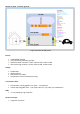


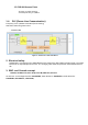
Table Of Contents

1.3.3 Circuit diagram of the module
Figure 5: Circuit diagram of the WLAN/WiFi module
1.3.4 COM_BOARD PCB with “Murata LBEE6U4XQC-182” module
Figure 5a: Display PCB with Murata module (front-, and backside) this is the used WLAN/WiFi module
Detailed informations about the Murata module LBEE6U4XQC-182:
Duty cicle: daily maximum 8 hours, 30%
External connectors: non
Powering: no external power supply, integrated power supply by PCB with 3,8 V
Radio module diagram: not defined
Receiver
Sensitivity: -80 dBm for (2,4 and 5 GHz)
Protocol wire and wireless: 802.11.n (a, b, g, n, ac)
HW13, SW_C:2900 (without PLC), HW13, SW_C2901 (with PLC) *PLC means “Power
Line Communication” (different module)
Antenna information: integrated PCB antenna, see next pictures
CONFIDENTIAL
CONFIDENTIAL