
Data Sheet


REX12 Electronic Circuit ProtectorREX12 Electronic Circuit Protector
www.e-t-a.de
6
1830
4
Temperature factor / continuous duty
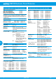
Time/current characteristic (T
amb
= +23 °C, U
B
= DC – 24 V) Basic trip curve and schematic diagram REX12
1000
100
trip time in seconds
...times rated current
10
1
0.1
0.01
0.001
0.8 1 1.2 1.4 1.6 1.8 2 2.2 2.4 2.6 2.8 3 I
SC
trip time in seconds
... times rated current trip curve REX12
1.000
100
10
1
0,1
0,01
0,001
0,8 1,0 1,2 1,4 1,6 1,8 2,0 2,2 2,4 2,6 2,8 3,0 3,2 3,4 I
KS
Schematic diagram REX12
blade fuse
semi-
conducto
r
4 A
LINE
4 A
LOAD
The time/current characteristic depends on the ambient tempera-
ture. In order to determine the max. load current, please multiply the
current rating with the temperature factor and consider the factor for
side-by-side mounting.
Temperature factor table:
ambient temperature [°C] 0 10 23 40 50 60
temperature factor 1 1 1 0.95 0.90 0.85
Note:
When mounted side-by-side, the devices can carry max. 80 % of
their rated load or a different rating has to be selected (see Technical
Information on www.e-t-a.de/ti_d)
With high temperatures, the load current warning threshold “warn limit
typically 0.9 x IN” will be reduced in accordance with the temperature
factor.
Selection of current rating of the circuit protector ≤ rating of power
supply.
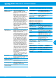
Dimensions with connection diagram: REX12-TA1-xxx / REX12-TB1-xxx/ REX12-TA2-xxx / REX12D-TE2-xxx
Mounting position REX…
preferred mounting position horizontal
snap-on socket for
rail EN 60715-35x7,5
operating
area
installation
area
1-channel 1-channel
Label e.g. from
Phoenix
Contact ZBF-12
2-channels 2-channels
GERMANY
98,5
92
80
7,5
contact arm
12,5
REX12-
TA1-1xx
DC24V
xA
Button for ON/OFF
or reset with
integral status
indication
2.1
LOAD +
REX12-
TB1-1xx
DC24V
xA
REX12-
TA2-1xx
DC24V
xA
xA
LOAD +
2.1 2.2
LOAD +
2.1 2.2
REX12-
TA2-1xx
DC24V
xA
xA
LOAD +
2.1 2.2
10A
9A
8A
7A
6A
5A
4A
3A
2A
1A
GERMANY