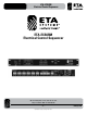
ETA-ECS6RM Electrical Control Sequencer ETA-ECS6RM Electrical Control Sequencer 1601 Jack McKay Blvd. • Ennis, Texas 75119 U.S.A. Telephone: 800-321-6699 • Fax: 800-996-3821 – 1 – Specifications are subject to change without notice. ETAsys.
ETA-ECS6RM Electrical Control Sequencer TABLE OF CONTENTS Safety..................................................................................................................................................................3 Introduction.........................................................................................................................................................5 Front Panel of ETA-ECS6RM............................................................................................
ETA-ECS6RM Electrical Control Sequencer SAFETY INSTRUCTIONS The lightning flash with arrowhead symbol within an equilateral triangle is intended to alert the user to the presence of uninsulated “dangerous voltage “ within the product’s enclosure that may be of sufficient magnitude to constitute a risk of electric shock to persons. CAUTION lifier AA35 ed 35W Engineered Sound CHINA RISK OF ELECTRIC SHOCK DO NOT OPEN ATTENTION ´ RISQUE DE DECHARGE ELECTRIQUE -NE PAS OUVRIR.
ETA-ECS6RM Electrical Control Sequencer CAUTION– WHEN INSTALLING THE PRODUCT • Plugging in or unplugging the power cord with wet hands may result in electric shock. • Never move the device with the power cord plugged into the wall, as damage to the power cord may result. • When unplugging the cord from the wall, grasp the plug, NOT the cord.
ETA-ECS6RM Electrical Control Sequencer INTRODUCTION Thank you for purchasing the ETA Systems ETA-ECS6RM Intelligent AC Power Sequencer. The ETA-ECS6RM (Electrical Controller Sequencer with Six Timing Sections with Remote Monitoring) modular system has been designed to meet most installation requirements for AC power distribution, equipment power conditioning and surge suppression protection. The compact 1RU unit features six sequential timing sections that can be activated via the unit, or remotely.
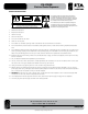
ETA-ECS6RM Electrical Control Sequencer ETA-ECS6RM KEY FEATURES • 6 Sequencer Timing Sections, 1,3, or 6 Second Intervals • 6 Independent ECM Connections • 6 Independent Contact Closures • Front Panel Digital AC Mains Voltage and Current Meter • Font & Rear Mounted XLR Connector for 12VDC Gooseneck LED Lamp • Qty 1 Atlas Power AP-GNL18 LED Gooseneck Lamp Included • External Switch Sequence Trigger Activation • External DCV Sequence Trigger Activation 5–24VDC • Abnormal AC Line Vol
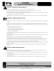
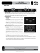
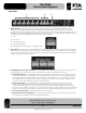
ETA-ECS6RM Electrical Control Sequencer FRONT PANEL 3 2 1 1. System Activation Switch – To activate or deactivate the system sequence, press the momentary switch once. There must be at least one ECM (Electrical Control Module) connected for a sequence to occur. If there are no Channel Status LEDs illuminated or voltage reading, no sequence will occur. The unit will only sequence through the number of ECM modules connected.
ETA-ECS6RM Electrical Control Sequencer 9 7 8 5 4 6 9 4. Channel Selection Switches – T hese push button switches allow the selection of the channel to be viewed at the Voltage and Current Meter. 5. Channel Selected LEDs – T here are six Channels in the ETA-ECS6RM and only one Channel Voltage or Current can be viewed at a time. The Channel selected and being viewed is indicated by the illuminated LEDs. 6. AC Mains Voltage and Current Meter – T here is only one Volt and Current Meter.
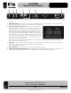
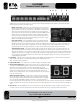
ETA-ECS6RM Electrical Control Sequencer REAR PANEL 1 2 3 1. ECM Control Ports – U p to 6 AC Main circuits can be activated or monitored by the ETA-ECS6RM. Each ECM control port connects to one of the following ECM modules: ETA-ECM20M, ETA-15SH, ETA-20SH, and the ETA-ECM20. For connection between the ETA- ECS6 and an ECM module use a 5 conductor cable that is a minimum of 22-gauge wire. We suggest using CAT5 cable due to the common availability.
ETA-ECS6RM Electrical Control Sequencer 4 6 5 7 8 4. Trigger Switches – Up to three ETA-ECS6RM units can be daisy chained together giving you 18 sequenced outputs. To do so you need to set the timing sequence of each unit. There are four dip switches that determine the position of the unit and the delay between sequencing. Follow the steps for setup. Master or Slave Unit – D etermine if you are daisy chaining two or three units together.
ETA-ECS6RM Electrical Control Sequencer ECM DATA WIRE AND DISTANCE There are four different types of ECM Modules that require the same interface connectivity to the ETA-ECS6RM. All ECM Modules can be interfaced with the ETA-ECS6RM. For connection between the ETA-ECS6RM and an ECM module, use a 5 conductor cable that is a minimum of 22-gauge wire. We suggest using CAT5 cable due to the common availability and low cost. Pay special attention to the port connections and DO NOT MISWIRE or damage may occur.
ETA-ECS6RM Electrical Control Sequencer ECM INDICATOR AND PART DESCRIPTION 1. Trigger / Status Port Pin Identification – a ll signals are of low voltage and current. DO NOT MISWIRE or damage may occur. + Requires a minimum of 5–24VDC to activate the module with 5mA of current. Note: The DCV can be supplied from any source. The EVS protection requires the ETA-ECS6RM for operation. G Circuit Ground, must be of the same circuit as the DCV source.
ETA-ECS6RM Electrical Control Sequencer ETA-ECS6RM ACCESSORY ITEMS AP-GNL18 – LED Gooseneck LAMP The Atlas Power AP-GNL18 is an optional LED Gooseneck Lamp and works with any of the ETA Systems 12VDC XLR base mount connectors. The length of the gooseneck is 16".
ETA-ECS6RM Electrical Control Sequencer ECM-RACEWY6 ECM Housing The ETA-ECM20 and ETA-ECM20M require an electrical housing. The ECM-RACEWY6 holds up to 6 ECM modules. There are standard ¾" and 1" electrical knockouts on the bottom of the raceway to support standard electrical mounting hardware. Since the Raceway can house 6 ECM modules there can be 6 separate 20A AC legs coming into the Raceway for a total of 120A of power distribution or it could be as simple as one 20A leg.
ETA-ECS6RM Electrical Control Sequencer ETA-ECM20 20A AC Control Module (No Current Monitoring) The ETA-ECM20 does not support the same Current monitoring or EMI/RFI Filter feature as the ETA-ECM20M, ETA-20SH and the ETA-15SH models have. However, it does support AC Spike and Surge Suppression, AC Mains Voltage monitoring, EVS circuitry and Remote Activation. In certain applications ETA Systems suggests using an ETA-ECM20 Module vs.
ETA-ECS6RM Electrical Control Sequencer ETA-ECS6RM WIRING CONFIGURATION Example 1 – ETA-ECS6RM wired to six ETA-ECM20 or ETA-ECM20M Modules using an ECS-KSW6 for remote activation. SYSTEM CONTROL 1601 Jack McKay Blvd Ennis, TX 75119 www.etasys.com Engineered in the U.S.A.
ETA-ECS6RM Electrical Control Sequencer Example 3 – Three ETA-ECS6RM wired to 18 ETA-ECM20 or ETA-ECM20M Modules. SYSTEM CONTROL 1601 Jack McKay Blvd Ennis, TX 75119 www.etasys.com Engineered in the U.S.A.
ETA-ECS6RM Electrical Control Sequencer EXAMPLES ETA-ECM20/M20RW MODULE WIRING CONFIGURATIONS The ETA-ECM20/M20RW is designed to be mated with the ECM-RACEWY6 housing and the ETA-ECS6RM controller. The specific job AC power requirements and power distribution layout will dictate how the ETA-ECM20M Modules are wired into the Raceway. Each ECM Module can be wired as a single 20A run or in a parallel configuration as illustrated below.
ETA-ECS6RM Electrical Control Sequencer TROUBLESHOOTING Note: All troubleshooting should be done by a certified electrician. Issue 1 – ECM Module Incoming AC LED is not illuminated. Possible Cause #1 Incoming AC mains circuit breaker has tripped due to excessive load. Action Needed Check the AC outlet that the ETA-ECS6RM is plugged into for proper voltage. If no voltage is present check to see if the AC outlet is on a GFI, check to see if it was tripped.
ETA-ECS6RM Electrical Control Sequencer Issue 5 – E TA-ECS6RM Channel Activation Status LED is Flashing Green and AC Power and Active LED at the ECM Module is Illuminated. Possible Cause The AC Mains Voltage at the ECM Module reached between 127VAC-132VAC or the voltage dropped between 101VAC- 107VAC. Action Needed The ETA-ECS6RM must be re-sequenced to turn off the LED. Measure the AC Mains before the ECM Module.
ETA-ECS6RM Electrical Control Sequencer ETA-ECS6RM SPECIFICATIONS General Type Power Sequencer Controller Sequencer Sections 6 Relay Sections 6 Sequence Timing Unit Settings of 1, 3 or 6 Seconds Unit Link 3 Power Supply External Wide Rage 100V–240VAC, UL Approval Power Consumption .8W RoHS Compliant Yes Dimensions H 1.75" x W 19" x D 10" Weight 7 lbs - 3.
ETA-ECS6RM Electrical Control Sequencer NOTES 1601 Jack McKay Blvd. • Ennis, Texas 75119 U.S.A. Telephone: 800-321-6699 • Fax: 800-996-3821 – 22 – ETAsys.com Specifications are subject to change without notice.
ETA-ECS6RM Electrical Control Sequencer NOTES 1601 Jack McKay Blvd. • Ennis, Texas 75119 U.S.A. Telephone: 800-321-6699 • Fax: 800-996-3821 – 23 – ETAsys.com Specifications are subject to change without notice.
ETA-ECS6RM Electrical Control Sequencer LIMITED WARRANTY All products manufactured by ETA Systems are warranted to the original dealer/installer, industrial or commercial purchaser to be free from defects in material and workmanship and to be in compliance with our published specifications, if any. This warranty shall extend from the date of purchase for a period of one year. Additionally, fuses and lamps carry no warranty.