
Owner's manual


ETC
®
Setup Guide
Sensor
®
3 Battery Backup Unit Installation Guide
Sensor3 Battery Backup Unit Installation Guide Page 1 of 4 Electronic Theatre Controls, Inc.
Corporate Headquarters
3031 Pleasant View Road, P.O. Box 620979, Middleton, Wisconsin 53562-0979 USA
Tel +608 831 4116
Fax +608 836 1736
London, UK
Unit 26-28, Victoria Industrial Estate, Victoria Road, London W3 6UU, UK
Tel +44 (0)20 8896 1000
Fax +44 (0)20 8896 2000
Rome, IT
Via Pieve Torina, 48, 00156 Rome, Italy
Tel +39 (06) 32 111 683
Fax +39 (06) 32 656 990
Holzkirchen, DE
Ohmstrasse 3, 83607 Holzkirchen, Germany
Tel +49 (80 24) 47 00-0
Fax +49 (80 24) 47 00-3 00
Hong Kong
Rm 1801, 18/F, Tower I Phase 1 Enterprise Square, 9 Sheung Yuet Road, Kowloon Bay, Kowloon, Hong Kong
Tel +852 2799 1220
Fax +852 2799 9325
Service:
(Americas) service@etcconnect.com
(UK) service@etceurope.com
(DE) techserv-hoki@etcconnect.com
(Asia) service@etcasia.com
Web:
www.etcconnect.com
QSF 4.1.9.1
Copyright © 2010 ETC. All Rights Reserved.
Product information and specifications subject to change.
7140M2180
Rev A
Released 2011-12
Introduction
This guide illustrates installation of the Sensor
®
3 Battery Backup Unit. This unit should be placed
in the vicinity of your Sensor3 dimmer racks.
The Sensor
®
3 Battery Backup Unit provides battery power to CEM3 control modules for up to 45
minutes during power outages, thereby facilitating an instantaneous recovery after power has
been restored. Each Battery Backup Unit may be fitted with one or two batteries; each battery
feeds one Sensor3 rack.
Required tools:
• Slotted screwdriver
• Precision slotted screwdriver
• No. 2 Phillips screwdriver
• Small extension (dental) mirror
• Wire strippers for 14-18 AWG (1.5-2.0mm
2
) wire
•Wire cutters
Required materials (not provided):
• Appropriate mounting hardware for attaching unit to wall
• 14-18 AWG (1.5 - 2.0mm
2
) twisted pair of adequate length for wire run
• 3/4” or smaller conduit of adequate length for wire run
• Conduit sleeves (2)
Procedure
This procedure is broken down into the following subsections:
Preparation on page 1
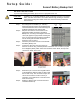
Mount Unit to Wall on page 2
Install Conduit from Unit to Sensor3 Rack on page 2
Connect the Battery Leads on page 2
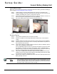
Run Wire from Unit to Rack on page 3
Install Battery Pack(s) on page 4
Finishing Touches on page 4
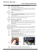
Preparation
Step 1: Turn off power to the rack. Before removing dimmer or control modules for
service, de-energize main feed to dimmer rack and follow appropriate Lockout/
Tagout procedures as described in NFPA Standard 70E. It is important to note
that electrical equipment such as dimmer racks can present an arc flash safety
hazard if improperly serviced. This is due to available large short circuit
currents on the feeders of the equipment. Any work on energized equipment
must comply with OSHA Electrical Safe Working Practices.
WARNING:
RISK OF ELECTRIC SHOCK! Failure to disconnect all power to the rack
before working in the rack could result in serious injury or death.