
Owner's manual


Setup Guide:
Sensor3 Battery Backup Unit
Sensor3 Battery Backup Unit Installation Guide Page 2 of 4 Electronic Theatre Controls, Inc.
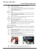
Step 2: Remove the eight modules above the backplane and CEM3 slot.
Step 3: Remove the CEM3 module.
Step 4: Open and unpack the Battery Backup Unit.
Step 5: Using a slotted (flat head) screwdriver, loosen and remove the two thumbscrews that
hold the battery pack(s) in the unit. Save the thumbscrews as you will need them to
reinstall the battery pack(s) later.
Step 6: Remove the battery pack(s) from the unit.
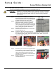
Mount Unit to Wall
Step 1: Choose an acceptable and accessible wall location for the Battery Backup Unit in the
vicinity of the Sensor3 rack(s) to be backed up.
Step 2: Hold the unit level against the wall and mark the wall through the four mounting holes
in the back of the unit.
Step 3: Attach the unit to the wall using the appropriate mounting hardware (not provided).
Step 4: Make sure the unit is secure before connecting conduit.
Install Conduit from Unit to Sensor3 Rack
Step 1: Using one of the available knockouts in the Battery Backup Unit, connect conduit
using a 3/4” conduit sleeve.
Step 2: Select an appropriate and available knockout in the Sensor3 rack that you intend to
backup. Connect the conduit to the rack using an appropriate conduit sleeve for the
chosen knockout.
Step 3: Repeat this process if backing up a separate Sensor3 rack is desired.
Connect the Battery Leads
In order to prevent premature battery drain, the battery pack or packs for this unit are shipped with
the leads disconnected. You must first open the battery pack(s) and connect the wire leads to the
appropriate terminals.
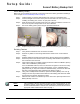
Step 1: Open the rear cover of the battery pack using a No. 2 Phillips screwdriver. There are
six screws on each battery pack.
Step 2: Locate the plastic bag containing the wire harness for the battery terminals. Remove
the harness from the bag.
Step 3: Connect the red harness wire to the positive (+) terminal and the black wire to the
negative (-) terminal on the battery pack.
Step 4: Replace the battery inside the battery pack housing.
Step 5: Connect the other end of the wire harness to the circuit board connector next to the
battery pack (indicated below). The connector is keyed and can only fit one way.
Step 6: Replace the battery cover using the six screws removed earlier.
Step 7: Repeat the process for other battery packs being installed in the system.
Connect wire harness to
circuit board here (Step 5)
Connect Red
wire here
Connect Black
wire here