
Owner's manual


Setup Guide:
Sensor3 Battery Backup Unit
Sensor3 Battery Backup Unit Installation Guide Page 3 of 4 Electronic Theatre Controls, Inc.
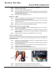
Run Wire from Unit to Rack
If you are only installing one battery pack, use the “A” (left) side of the unit.
Step 1: Run a length of 14-18 AWG (1.5 - 2.0mm
2
)
twisted pair wire through the conduit between the
unit and the Sensor3 rack. Include extra length to
facilitate terminations and working slack.
Step 2: Strip the wire ends and connect them to the
appropriate header terminals in the Battery
Backup Unit, according to the diagram on the unit
cover (see graphic at right). Before inserting the
wire, you must first insert a precision screwdriver
into the rectangular slot below the desired
terminal in order to open it.
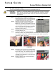
Step 3: Find the 2-pin Phoenix connector included with
the Battery Backup Unit.
Step 4: Connect the wires from the unit to the 2-pin
Phoenix connector using a slotted precision screwdriver. Pin 1=Positive (red) and
Pin 2=Negative (black). When held in the orientation shown below, the top of the
connector is visible. This is Pin 1.
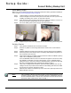
Step 5: Return the 2-pin connector to its original location
on the backplane. Make sure that you align it with
the red wire on top. The connector is keyed, but
can be forced onto the mount incorrectly. If
necessary, use a small mirror to view the mount
when reconnecting.
Step 6: Repeat for “Rack B” side if a second Sensor3
rack will be backed up.
CAUTION:
Installation on an installed CEM3 will require negotiating load wires, termination
wires, and other obstructions. Use caution when moving, bending or otherwise
manipulating existing wires inside of the rack. This will avoid any inadvertent
disconnections.
Rack A
Side
Rack B
Side
Top of connector
(Pin 1 side)
Wires terminated with
Pin 1 (red) on top and
Pin 2 (Black) on bottom
Connect 2-Pin connector
to rear of backplane