
Instruction Manual

ETC
®
Setup Guide
Sensor
®
3 Ride-thru Option Module Installation Guide
Sensor3 Ride-thru Option Module Installation Guide Page 1 of 2 Electronic Theatre Controls, Inc.
Corporate Headquarters
3031 Pleasant View Road, P.O. Box 620979, Middleton, Wisconsin 53562-0979 USA
Tel +608 831 4116
Fax +608 836 1736
London, UK
Unit 26-28, Victoria Industrial Estate, Victoria Road, London W3 6UU, UK
Tel +44 (0)20 8896 1000
Fax +44 (0)20 8896 2000
Rome, IT
Via Pieve Torina, 48, 00156 Rome, Italy
Tel +39 (06) 32 111 683
Fax +39 (06) 32 656 990
Holzkirchen, DE
Ohmstrasse 3, 83607 Holzkirchen, Germany
Tel +49 (80 24) 47 00-0
Fax +49 (80 24) 47 00-3 00
Hong Kong
Rm 1801, 18/F, Tower I Phase 1 Enterprise Square, 9 Sheung Yuet Road, Kowloon Bay, Kowloon, Hong Kong
Tel +852 2799 1220
Fax +852 2799 9325
Service:
(Americas) service@etcconnect.com
(UK) service@etceurope.com
(DE) techserv-hoki@etcconnect.com
(Asia) service@etcasia.com
Web:
www.etcconnect.com
QSF 4.1.9.1
Copyright © 2010 ETC. All Rights Reserved.
Product information and specifications subject to change.
7140M2160
Rev A
Released 2011-02
Introduction
This guide illustrates installation of the Sensor
®
3 Ride-thru Option Modules to the rear of the
CEM3 backplane. The Ride-thru Option Module prevents the CEM3 from shutting down in the
event of a brief drop in supply voltage (brown out).
Installation on an installed CEM3 will require negotiating load wires, terminations wires, and other
obstructions. Use caution when moving, bending or otherwise manipulating existing wires inside of
the rack.
Installation Procedure
Step 1: Power down the rack. Before removing dimmer or control modules for service,
de-energize main feed to dimmer rack and follow appropriate Lockout/Tagout
procedures as described in NFPA Standard 70E. It is important to note that
electrical equipment such as dimmer racks can present an arc flash safety
hazard if improperly serviced. This is due to available large short circuit
currents on the feeders of the equipment. Any work on energized equipment
must comply with OSHA Electrical Safe Working Practices.
Step 2: VERIFY that no power is connected to the rack
by checking voltages for all combinations
between the phase bars, neutral and ground.
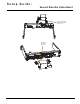
Step 3: Plug the wire harness into the module making
sure that the wires run towards the center bulk of
the module (see graphic at right). If attached in
the wrong orientation, the module will not
function.
Step 4: Connect the orange wire harness connector to
the appropriate connector on the rear of the
backplane (see illustration next page).
Step 5: Locate the holes in the rear of the backplane using a small mirror (included in the kit).
Step 6: Screw the module to the appropriate holes in the rear of the backplane (see
illustration next page).
Note:
If you are adding this module while upgrading a dimmer rack to be a Sensor3
CEM3 rack, be sure to attach the dimmer output ribbon cables before following
this procedure. It is very difficult to connect the ribbon cables after the ride-thru
option module has been installed.
WARNING:
RISK OF ELECTRIC SHOCK! Failure to disconnect all power to the rack
before working in the rack could result in serious injury or death.