TM TM Zoom CE Assembly Guide
Electronic Theatre Controls, Inc.
TM TM and Zoom CE Assembly Guide Contents Lamp socket assembly ................................................................... 5 Lens holder assembly ..................................................................... 9 Maintenance ................................................................................. 11 Shutter assembly .......................................................................... 13 Final assembly ..........................................................................
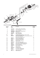
19 25 10 20 9 12 7 2 21 11 29 17 24 23 14 5 8 1 6 18 13 27 15 4 3 16 22 28 Lamp socket assembly Reference number Part number Description 1 2 3 4 5 6 7 8 9-11 9 10 7060A3055 7060A3057 7060A4007 7060A4008-02 7060A4011 7060A3011 7060A3012 HW748 M718 W330-03 W330-04 Housing, socket, casting, painted Socket, light baffle casting, painted Knob, X-Y, lamp set Knob, Z, lamp set w/female insert Bushing, cup Hub, index, casting Spring, lamp retainer Spring, compression Complete TP22 450 degree-
Lamp socket assembly Tools required: Open-end adjustable wrench or a 7/16" socket, needle-nose pliers, screwdriver. Figure 1 1. Install the screw (20) into the light socket baffle casting as shown in figure 1. (Also see figure 7 on page 7.) 19 2. Insert the bolt (19) through the light baffle socket casting (2). 3. Install the green ground wire assembly (21) on the bolt (19) with the prongs on the crimped connector toward the casting. Run the wire through the indent in the lip around the bolt hole.
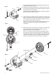
9. Insert the knurled head screw (13) through the housing socket casting (1) as shown in figure 4. Figure 4 14 10. Install the ground spring (23) onto the screw and secure it with the Southco flat retaining ring (14). Install the Southco ring with its prongs away from the casting. 23 13 Note: Use pliers to straighten the Southco retaining ring (14) if it bends when you install it on the bolt. 11.
13. Place the spring (8) on the protrusion on the inside of the index hub (6). 14. Insert bolt (19) through the light socket baffle (2), thread nut (12), through spring (8) and through the index hub (6) of the housing socket (1), joining the two castings. Make sure wires are not pinched between the two pieces. 15. Before proceeding, check again to make sure the wires are still positioned as indicated in figure 5. Adjust if necessary. 16.
Lens holder assembly Reference number Part number Description required 1 2 3 4 5 6 7 8 9 10 11 12 7062A3005 7062A3017 7062A3018 7062A3019 7062A3020 7062A4001 7062A4002 7062A4003 7062A4008 7062A4009 7062A3027 7062A3026 13 14 HW751 7060A4010 7062A3029 HW196 Lens holder, 26° Lens holder, 36° Lens holder, 50° Lens holder, Zoom, forward Lens holder, Zoom, rear Lens, 26°, “black dot” Lens, 36°, “white dot” Lens, 50°, “yellow dot” Lens, Zoom, forward Lens, Zoom, rear, black Lens cover, Zoom, front, 25°– 50
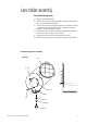
Lens holder assembly Fixed Field Angle Lens 1. Snap on the bushings (14). 2. Position the lens by centering the paint dot between the three tabs, as shown below in figure 8. 2. Center one Tinnerman clip (15) on each tab, as shown in Figure 9, and press clip until it is fully seated. If clips are in uneven positions, lens will be tilted or loose. 3. Firmly press each clip down and roll it away from the center of the lens to ensure contact on lens surface. 4.
Zoom Front Lens Assembly 1. Position the lens (9) between the lens holder (4) and the lens cover (11) so that the convex side of the lens faces the lens holder, as shown in Figure 9. 2. Align the holes in the lens cover with the holes in the lens holder as shown below. 3. Secure the lens cover and the lens to the lens holder using screws (14) and locking nuts (15). Tighten securely to ensure no lens movement. Figure 9 4. Snap the bushings (17) onto the lens holder assembly as shown.
Maintenance Cleaning lenses 1. Dampen a clean, lint-free cloth with vinegar or household ammonia. You may use water, but it will leave spots which may be removed by polishing the lens gently with a clean, dry cloth. Warning: Never use glass and window cleaner or any abrasive material to clean the lens. Glass and window cleaners will stain the lens surface. Abrasive materials (such as steel wool) will damage the surface of the lens. 2. Starting from the center, gently wipe the lens.
1 3 4 2 Shutter assembly Reference number 1 2 3 4 5 6 12 Part number Description 7062A2002 7062A3016 7062A3010 7062A3030 7062A3031 HW754 Shutter blade assembly Plate, divider Plate, gate (middle) Plate, divider with dimples Plate, support, spring (see figure 12) Spring, shutter (see figure 12) Quantity required 4 1 1 1 1 4 Electronic Theatre Controls, Inc.
Shutter assembly Tools required: None 1. Place the bottom divider plate (2) on a flat surface. Note: The notches on the divider plates must line up with each other. Figure 11 1 3 Warning: Divider plate edges are sharp. Handle with caution! 4 2. Place two shutter blades (1) on top of plate (2), handles facing outward. Note: Install shutter blades with the rounded sides facing the same direction. 3. Place the middle divider plate (3) on top of the two shutter blades. 4.
12 21 20 13 9 17 10 18 23 1 14 24 25 11 4 3 7 6 2 5 26 27 8 16 15 19 9 4 22 Final assembly Reference number 1 2 3 4 5 6 7 8 9 10 11 12 13 14 15 16 17 18 19 20 21 22 23 24 25 26 27 14 Part number Description Quantity required 7062A3002 7062A3004 See page 4 HW8201 7061A3005 7062A4010 7062A3007 HW750 See page 8 7062A3009 HW8144 HW5193 HW5125 HW5126 HW391 See page 13 7062A3013 HW8200 7062A3014 7062A3015 HW372 HW3165 HW307 HW348 HW349 HW4117 HW779 Barrel, left casting Barrel, right cast
Final assembly Tools required: Phillips head screwdriver. Note: Left and right designations are your left and right as you look at the front (gel plane) of the unit. 1. Place the left barrel casting (1) face up on your work surface with the colorframe end to your right. 2. If necessary, place spring (17) over post in right and left castings (1 and 2). Secure with the push-on retainer (18). 3.
Electronic Theatre Controls, Inc. Americas Middleton, Wisconsin 53562 • USA • Tel: (+1) 608 831 4116 • Fax: (+1) 608 836 1736 • (+1) 800 775 4382 • service@etcconnect.com Europe London • England • Tel: +44 (0)20 8896 1000 • Fax: +44 (0)20 8896 2000 • service@etceurope.com Asia Hong Kong • Tel: (+852) 2799 1220 • Fax: (+852) 2799 9325 • service@etcasia.com International 3030 Laura Lane • Middleton, Wisconsin 53562 • USA • Tel: (+1) 608 831 4116 • Fax: (+1) 608 836 1736 World Wide Web http://www.etcconnect.