
Instruction Manual

Electronic Theatre Controls
North America
3030 Laura Lane • Middleton, Wisconsin 53562 • USA • Tel: (+1) 608 831 4116 • Fax: (+1) 608 836 1736
Europe
5 Victoria Industrial Estate • Victoria Road • London W3 6UU • Tel: (+44) 181 896 1000 • Fax: (+44) 181 896 2000
Asia
Room 605-606 • Tower III • Enterprise Square • 9 Sheung Yuet Road • Kowloon Bay • Hong Kong • Tel: (+852) 2799 1220 • Fax: (+852) 2799 9325
World Wide Web:
http://www.etcconnect.com •
Email:
mail@etcconnect.com
Specifications subject to change. Source Four HID is protected by US patent numbers 5,446,637; 5,345,371 and 5,775,779. US and International Patents Pending.
Copyright 1999. Revised 11/99.. Part number: 7060M1017
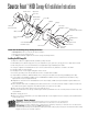
Source Four HID
Canopy Kit Installation Instructions
Please note the following safety warnings before use:
•
Turn off power
at main fuse or breaker box before installation
• Wiring must meet local and national code
• Use
only
the hardware supplied to mount the canopy kit and light fixture
Installing the HID Canopy Kit
1.
Attach the J-Box (not supplied with kit) to building ceiling structure.
2.
Run ballast power cable through jam nut 3, yoke stop bracket, yoke, jam nut 2, canopy, jam nut 1, nipple and cross bar.
3.
Run wiring from the Source Four HID fixture (not supplied) through the ballast power cable.
4.
Using the supplied cross-bar-attachment 1/2” screws (2) and washers (2), attach the cross bar to the J-Box.
5.
Thread in nipple to desired length.
6.
Thread jam nut 1 over the nipple and tighten with a wrench.
7.
Insert the grounding screw into pre-drilled hole in the cross bar marked “GND”
8.
Strip insulation from Green, Black and White wires coming from the branch circuit wiring and ballast power cable
9.
Connect branch circuit Black and White wires to ballast Black and White wires, as indicated in the illustration, using
approved wire nuts (not supplied with kit).
10.
Wrap branch circuit Green wire and ballast Green wire around body of GND screw per illustration. Tighten GND screw
with a screwdriver.
11.
Place the black strain relief over ballast power cable, between wire connections and end of nipple. Snap the two halves of
the strain relief together using pliers. Push all wiring and connections into the J-Box.
12.
Place canopy over the nipple, and loosely secure with jam nut 2.
13.
Position the small hole in the canopy so that it aligns with the pre-drilled hole in the cross bar, and secure with 1-1/4” Yoke-
stop hardware.
14.
Tighten canopy jam nut 2.
15.
Place the Source Four HID fixture yoke (not supplied with kit) over the nipple and secure using the yoke-stop bracket and
remaining jam nut 3.
J-Box
(Not included)
Jam nut 2
Nipple
Ground
screw
Cross-bar-attachment
hardware (1/2”)
Cross bar
Jam nut1
Jam nut 3
Yoke-stop
hardware (1-1/4”)
Fixture yoke
(Supplied with fixture)
Yoke-stop
bracket
Canopy
Black plastic
strain relief
Black wires
Approved
wire nuts
White wires
Green Ground
wires
Ballast power
cable
Wires from
fixture
™