ACCESS CONTROL SOLUTION Eternity 4 Eternity 5 Manual
TABLE OF CONTENTS SECTION 1 GENERAL OVERVIEW ............................................................................................................................... 4 I. Foreword ................................................................................................................................................................. 4 About This Manual .............................................................................................................................................
Activation / Expiration Date Setting ......................................................................................................................... 23 Exception Date Setting.............................................................................................................................................. 24 IV. Mission Management............................................................................................................................................
Section 1 General Overview I. Foreword About This Manual This manual is designed for users of Eternity 4 and Eternity 5. All installation, setup, operational information, procedures, screen captures, and other relevant materials are contained in this manual. Safety Warnings and Cautions When handling a printed circuit board (PCB), guard against possible static discharges by touching a grounded object BEFORE touching the board. Static shock could cost unexpected damage of the board.
III. General Lock Spec This page shows the similar specifications of the Eternity 4 and Eternity 5. Keypad: 12 all weather numeric keypad Keypad Functions: Permanent codes, Temporary codes, one-time service codes Power Supply: 4 standard AA batteries with a weatherized battery pack for all weather conditions Power Supply Life Expectancy: 10,000 operations, low battery warning when system drops below 4.
IV. Eternity IV Datasheet (Heavy Duty keypad Lock) Hardware Spec PARAMETER Lock Weight Working Current Idle Current Lock Back Time Working Voltage Low Battery Warning Power Source Keypad Handle Door Thickness Keyway Packed Weight Packed Size CTN Weight CTN Size DETAIL 6 Lb <10 mA 5 µA 5 (1 – 25) Seconds 4.8-6.4V 4.
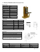
Door Prep Parts List 1 2 3 4 5 6 7 8 iButton Reader Keypad Outside Lock Housing Outside Lever Override Cylinder Outside Gasket Latch Inside Gasket 9 10 11 12 13 14 15 Inside Mounting Plate Batteries Housing Cover Inside Lock Housing Inside lever Spindle Strike Plate Dust Boot Page 7 of 36
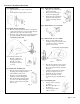
Eternity IV Installation Instruction Step 1. Install the latch • Insert the latch into 1″ hole on edge of the door. • Secure the latch in place with two screws. Step 4. Install inside lock housing • Plug the power cable into the inside lock housing. • Place inside lock housing on top of the mounting plate, • Ensure the square spindle into inside lever hub. Secure the inside lock housing with two screws. Fig. 5 Fig. 1 Step 5. Install inside lever door handle. Step 2.
V. Eternity V Datasheet (Medium Duty keypad Lock) Hardware Spec PARAMETER Weight (Lock only) Working Current Idle Current Motor Running Time Working Voltage Low Battery Warning Power Source Keypad Handle Door Thickness Keyway Dimension (1ps) Dimension (8pcs/box) Package Weight (1) Weight (8pcs/Box) DETAIL 4.2 Lbs 250 mA 15 µA 0.4 Second 4.2-6.4V 4.
Major Lock Parts Back View Installation 1. 2. 3. 4. 5. 6. 7. 8. 9. 10. 11. 12. 13. 14. 15. 16. 17. 18. 19. 20. 21. 22.
Eternity-V-Installation Step 1 Insert the latch into door hole. Secure the latch with two screws. Step 2 Insert the square shaft (A) into the center hub (B) (Fig 1). Insert the position pin into the hole on the center hub to secure the square shaft. Bend the end of position pin around the center hub to secure the pin in place. (Fig 2) Enlarged Fig 1 Fig 1 B Fig 2 A Step 3 Screw in and tighten the two fastener extensions (C) into the front lock fastener posts located on both side of the center hub.
Step 5 Attach the battery plate onto the door, with the rubber gasket between the door and battery plate. Make sure the power plug go through the hole on the plate. Secure the battery plate to front lock fastener post with 2 screws. Fasten upper fastener post (Optional) (Fig 5) Step 6 Install batteries, and plug in the power cable. Secure the back lock housing onto the battery plate. Fasten with 2 screws.
Eternity-V-Mortise-Installation Step 1 Insert the lock case into mortise pocket. Secure the lock case with two screws. Step 2 Insert the square shaft (A) into the center hub (B). (Fig 1) Insert the position pin into the hole on the center hub to secure the square shaft. Bend the end of position pin around the center hub to secure the pin in place.
Step 5 Attach the battery plate onto the door, with the rubber gasket between the door and battery plate. Make sure the power plug go through the hole on the plate. Secure the battery plate with 3 screws; fasten to front lock fastener extension post and upper fastener post (Fig 5) Note: upper fastener post is optional. Fig 5 Step 7 Place the override cylinder into front handle housing, insert override key through the hole into cylinder. Turn the override key 90° clockwise.
1. 2. 3. 4. 5. 6. 7. 8. 9. 10. 11. 12. 13. 14. 15. 16. 17. 18. 19. 20. 21. 22.
Section 2 Eternity Software Guide 1. Software Setup The Eternity Software works the same for both Eternity 4 and Eternity 5. Operating System Eternity software is compatible with Microsoft Windows 98/2000/XP/Vista. All software must be installed using Windows administrator account, but all level Windows users can use the program. Failure to install the applications may result in error messages and an incomplete installation.
License Name: Input the name of your company User Name: dallas Password: ibutton Default User Name and Password can be modified but can’t be deleted. Change System Password The default system password is 000000(6 Zeros). It is mandatory to change and remember the facility system password when the user is ready to use this software. It is highly recommended that the system password need to be changed from the default setting for security purpose. 2. Access Control Management I I.
Steps to set up a new lock mission 9 Snap the program key (DS1977) onto the USB blue dot receptor, login to the software and click on the New Lock Setup icon, and click issue key. Click ok to clear the pop up warning message box. 9 Now take the program key to the lock, hold the reset button on the lock until there are two beeps and a solid green light; while the led is solid green, touch the program key to the iButton reader on the lock, and there will be two beeps to show that it worked.
II. User Setup Onsite User Setting ¾ Add/Edit user information To add/edit iButton / key code user, click “Add” button in the key setting menu, and following screen will pop up: To add iButton user, click ok and snap a user iButton key into the encoder. Click on the empty field of “Serial ID”, the iButton key ID will be detected by the system and automatically entered. If the user key already exists in the system, the software will pop up a warning. No duplicate keys are allowed in one system.
¾ Assign Onsite user to lock ¾ Single-lock key Assignment Mission: This mission is to assign iButton keys and user codes to one lock. o o o o o o Select lock from lock list Change the time shift if needed Click to change the ‘Selected’ Column for the assigned users to the lock Snap in programming key Click “Issue Key” Complete the mission by touching the programming key to the lock reader, wait till you hear a double beep. 9 Multiple Lock Assignment This mission is to assign key list to multiple locks.
Remote User Code Setting ¾ Create remote Access Code Click on the “Remote Code” icon, the following screen will show: 9 Click on Lock Name field, the list of existing locks window will pop up, selects the lock from the list. 9 Fill in the Guest First, and last name. 9 Select the starting date and ending date you want the temporary codes to have access to the lock. You can select pre defined check in/out time from the list (up to 4 set of check in/out time) 9 Click on the “create code” icon.
¾ One Time Service code Up to 16 one-time service codes can be generated during the same time window. Note: the access codes and service codes are accurate to the hour. Setting an ending time of 3:30 will prevent the code from working any time after 3:00 on that date. 3. Access control Management II III. Time Setting Time shift, activation/expiration, and exception date settings can be applied to keys by doing a key assignment and selecting the desired settings.
• • • • Storehouse Mode: In this mode, the Lock will lock back in a few seconds (0.1-25.5 seconds). Classroom Mode: In this mode, the lock does not lock back. The use of a valid iButton or code simply makes the lock go from unlocked to locked or locked to unlocked. Lock Mode: In this mode, the lock will automatically lock at the setting time. Unlock Mode: In this mode, the lock will automatically unlock at the setting time.
Exception Date Setting This function is used to set restrict access during periods such as holidays, facility shutdowns, vacations. The first group set as No Limit default setting. The holidays can be set as a single day or multiple days. The selected user iButton keys or codes will be restricted from access for all of the exception dates. IV. Mission Management Click “Mission Management” on the main screen and select “Maintenance Mission” from the drop down menu.
Set Time Key This step uses the DS1904 or DS1994 to set the real time of the lock Tip: Other than DS1904/1994 real time key, the DS1977 program key can also set the time of the lock. But program key will cause time delay since programming the mission key and programming the lock will take time. We recommend using the DS 1904/1994 real time key if the programming process takes more than 3 minutes.
Lockout Key Lockout forbids all assigned keys/codes from operating the lock. Apply any Lockout key to put the lock in Lockout Mode, and apply again to release the Lockout Mode. To apply the key, snap the program key into the encoder, select open door or close door, press the “Issue Key” button, and then press the program key to the lock to set the Lockout Mode. There are two types of Lockout Modes. ¾ Lockout and Open: Lock will stay unlocked and lockout all users.
V. Audit Trial Click “Mission Management” on the main screen toolbars and select “Advanced Mission” from the drop down menu, select “Get Audit Trial”: 1. 2. 3. 4. 5. Snap the program key to the encoder and click on “Issue Key” button. A “Write Get Audit Trail key OK” message will pop up. Click OK to close the screen. Unplug the program key and touch the lock’s iButton reader, you will hear a long series of chirps followed by two beeps. Snap the program key back to the encoder and click “Read key” button.
VI. History Lock Audit History Click “History” and choose “Lock Audit History” from drop down menu, the following screen will pop up: Here’s how to view the saved data: 1. On “Query By” give the time window of the audit records, and check the key words. 2. On “Order By” check the key words of the records order. 3. Click “Query” button, the records will show on the screen.
4. Click “Export” to save a copy of the audit trail and records the information to an Excel file. Access Code history All the remote temporary codes and one-time service codes will be saved for future reference Operator Log When select “Operator Log”, the following screen will show: Using the same method to manage the operator log, and audit the operators’ activity. Section 3 Non-software Guide This section is for the use of either the Eternity 4 or Eternity 5 without software.
I. General Information: • • • • • Exit Setting: Enter * to exit the setting procedure, or wait for 10 seconds Low Battery warning: When the voltage drops below 4.8V, after entering a valid code, the red LED will flash and beep five times. Unlock: Green light flashing twice and Beeps twice. Lock: Red Light flashing three times, and beeps three times. Reset: To set the lock back to default (123456), press and hold the reset button for about 10 seconds (3 beeps with LED blink red).
• • One time service code: One time code, # Manual key: Turn the override key 90 degree clockwise, then turn the handle V. Terms: Program code: The program code puts the lock into a programming mode. It will not lock/unlock the lock. When #, program code, # is entered, the red LED starts to flash indicating the lock is in a programming mode. If more than 6 seconds pass in between programming entries, the lock will return to normal operational state.
How to add one user access code (with time restriction) Function Code: 01# ¾ {#Master code#}+{01#}+{user code#}+{yymmddhhmm#(start time)}+{yymmddhhmm#(ending time)} How to add multi-user code (with time restriction) Function Code: 01# ¾ {#Master code#}+{01#}+{user code#(1)}+{yymmddhhmm#(start)}+{yymmddhhmm#(ending time)} + {user code#(2)}+{yymmddhhmm#(start)}+{yymmddhhmm#(ending)} …and so on How to add one iButton key (no time restriction) Function Code: 01# ¾ {#Master code#}+{01#}+{touch iButton # #}
How to delete user code or iButton key with index # Function Code: 44# ¾ {#Master code#}+{44#}+{index#} How to delete one user code / iButton key (without index number) Function Code: 46# ¾ {#Master code#}+{46#}+{user code#} (or iButton key) How to de-active user code / iButton key (without index number) Function Code: 48# ¾ {#Master code#}+{48#}+{user code} (or iButton key) How to In-active user code or iButton key without index number Function Code: 47# ¾ {#Master code}+{47#}+{user code} (or iButt
#23456# Master code 45# Function code 2222# User code 135# Mon/Wed/Fri 0830 Beginning time 1730# 4. Ending time 0800=8:00AM 1730=5:30PM Section 4 Case Study University Park Business Center, Denton, TX Problem: The Luxury Home Builders is one of the largest custom home / office builders in north Texas. One of the examples is the University Park Business Center.
Step 1: Time Setting, set Time Shift 3 from Monday to Friday, 6:30PM to 10:00PM, Saturday from 1:00PM to 10:00PM, and Sunday from 8:00AM to 9:00PM. Here is the timetable for the keys: Begin Time 6:30:00PM 6:30:00PM 6:30:00PM 6:30:00PM 6:30:00PM 1:00:00PM 8:00:00AM End Time 10:00:00PM 10:00:00PM 10:00:00PM 10:00:00PM 10:00:00PM 10:00:00PM 09:00:00PM Day of Week Monday Tuesday Wednesday Thursday Friday Saturday Sunday Step 2: Edit the Keys property in Key Setting. Set the Time Shift group to Time Shift 3.
Warranty Registration Form Customer Information: Date Purchased: Purchase From (company name): Model: Serial Number: First Name: Last Name: Daytime Phone: E-mail: Shipping Address: City: --------------------------------- State: -------------------------------- Zip Code: --------------------------- Mail Registration Form to: Inc Attn: Registration Dept PO Box 250128 Plano, TX 75025 ____________ Warranty and RMA Guidelines Receiving Your Order 1.