INSTALLATION GUIDE Eternity GAS WATER HEATERS MODELS 16-18-20-24-26 FOR EXTERNAL INSTALLATION ONLY 1
CONTENS IMPORTANT・・・・・・・・・・・・・・・・・・・・・ 2 FOR THE INSTALLER・・・・・・・・・・・・・・・・・ 2 FOR THE SERVICER・・・・・・・・・・・・・・・・・ 2 WITHOUT REMOTE CONTROLLER・・・・・・・・・ FOR THE PLUMBER・・・・・・・・・・・・・・・・・ 3 WITH ONLY MAIN SPECIFICATIONS・・・・・・・・・・・・・・・・・・ INTRODUCTION・・・・・・・・・・・・・・・・・・・ 3 REMOTE CONTROLLER・・・・・・・・・・・・ 18 4 WITH MULTIPLE REMOTE CONTROLLRE・・・・・・ 19 DIMENSIONS AND CONNECTION POINTS・・・・・・・ 5 SAFETY GUIDELINES・・・・・・・・・・・・・・・・ INSTALLATION・・・・・・・・・・・・・・・・・・・ 6 CONFIRM THE APPLIANCE SUITABILITY・・・・・・
FOR THE PLUMBER PLEASE NOTE this water heater is supplied factory set at 70°C outlet hot water temperature. This water heater does require a tempering valve to be installed to comply with AS3498 / 50C requirement. Please follow all the installation instructions in the Installation and operating instructions handbook and the following additional instructions for the water heater outlet connection. 1.
INTRODUCTION This manual provides information necessary for the installation, operation, and maintenance of the water heater. The model description is listed on the rating plate which is attached to the right side of the case of the water heater. (Please refer to p.7) Please read all installation instructions completely before installing this product. The Water Heater is an instantaneous, tankless water heater designed to efficiently supply endless hot water for your needs.
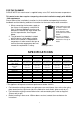
ACCESSORIES Check that the installation manual and screws are included with the unit. Screws × 4 Manual DIMENSIONS AND CONNECTION POINTS Model24 Model26 350 330 94 60 215 1 5 .7 37 19 182 HOT GAS GAS 542 HOT 4 4 .5 COLD 335 COLD POWER 84 34 133 Model16 Model18 Model20 520 25 POWER 41 HOT 49 COLD 490 198 GAS 124 350 330 94 170 137 1 5 .
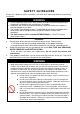
SAFETY GUIDELINES Ensure the following safety instructions are read and understood before commencing installation. @@@@@@@@@@@WARNING@@@@@@@@@@@ For the continuing safety of this water heater it must be installed and operated and maintained in accordance with manufactures instructions. Installation and service must be performed by a qualified installer (for example, a licensed plumber or gas fitter).
INSTALLATION The water heater requires careful and correct installation to ensure safe and efficient operation. This manual must be followed exactly. Read the “SAFETY GUIDELINES” and the “IMPORTANT” sections at the beginning of this manual. CONFIRM THE APPLIANCE SUITABILITY Check the gas type label and the rating plate for the correct gas type, gas pressure, water pressure and electrical rating for your application. Do not install this unit if these requirements can’t be met.
ABOUT SELECTING A INSTALLATION LOCATION Carefully read this section before installing, and when you select the location for install the water heater, you must follow these precautions exactly. @@@@@@@@@@@CAUTION@@@@@@@@@@@ This is a water heating apparatus only and the final fitness of water delivered is dependent upon the quality of water supplied to this system.
CLEARANCES FOR OUTDOOR HEATER LOCATIONS – AS5601 *Exemption from prescribe statutory requirements referred to in Figure 1 has been granted to allow multiple series of the Water Heaters to be positioned side by side.
GAS CONNECTIONS a@@@CAUTION@@@a POWER CORD GAS INLET SUPPLY GAS VALVE 1. Turn off the electric power to the water heater and manual gas valve located on the outside of the unit before beginning gas connection. 2. Confirm the position of the gas inlet. Do not connect water line to gas inlet. It may be critical damaged. SIZING AND CONNECTING Check the gas type label to make sure that the unit was built for the type of gas you will be using, and that the gas inlet pressure is within the appropriate range.
MEASURING INLET GAS PRESSURE AND TESTING GAS LEAKGAE The appliance and its gas connections must be measured inlet gas pressure and leak tested before placing the unit in operation for properly performing and safety. This is only to be done by a licensed professional. 1. Shut off the manual gas valve on the supply gas line. 2. Open a faucet. The unit should turn on and the gas in the gas pipe line should purge. Leave the faucet on to keep the unit running until the unit shut down due to lack of gas supply.
WATER CONNECTIONS @@WARNING@ @ DRAIN PLUG FILTER HOT WATER OUTLET GATE OR BALL VALVE ON INLET Do not reverse the hot outlet and cold supply line connections to the Water Heater as this will cause your heater to operate improperly. COLD WATER INLET All pipes, pipe fittings, valves and other components, including soldering materials, must be suitable for potable water systems.
ELECTRICAL CONNECTIONS 1. The water heater must be electrically grounded. Do not attach the ground wire to either the gas or water piping. Weather-proof Power Point 2. The water heater requires an AC 240V 50Hz electrical power supply and draws a current of 0.8A. 3. The weather-proof power point should be no more than 1 meter from the base of the water heater for easy access. 4. Install so that the electrical power can be switched off if necessary. 5.
REMOTE CONTROLLER (OPTIONAL) The water heater can be installed with up to three remote controllers. Each remote controller has two functions which can adjust the set temperature and indicate the error code on the remote controller. The set temperature can be adjusted only by remote controller which has the priority setting (When remote controller has the priority setting, PRIORITY lamp on remote controller is lit), and the other remote controller(s) display the set temperature.
REMOTE CONTROLLER INSTALLATION 1. Crimp the fork terminals to the wires. ・Minimum 18AWG wire (No polarity) ・Maximum 100m long Use the fork terminals REMOTE CONTROL WIRING Connector base 2. Attach the fork terminal to the connector base of the backside unit with two screws tight. 3. Put out wiring downward through the cable trench. 4. Attach the remote control on the wall with two attached screws. (If you need to attach the remote control to brittle, you should use the anchor plug.
CONNECTION OF REMOTE CONTROLLER WIRING TO THE WATER HEATER 1. Turn off the power supply to the water heater. 2. Remove the front cover from the water heater. There are 3 screws on the front cover. 3. Put the remote wires through the hole on the bottom of the unit's casing. 4. Remove the plastic cover and connect remote control wires to remote terminals directly. (There is no polarity in the terminations.) *DO NOT jump or short-circuit wires. Computer will be damaged. 5.
INITIAL OPERATION FOR YOUR SAFETY, READ BEFORE OPERATING: Check the GAS and WATER CONNECTIONS for leaks before firing it for the first time. Open the main gas supply valve to the unit using only your hand to avoid any spark. Never use tools. If the knob will not turn by hand, do not try to force it; call a qualified service technician. Forced repair may result in a fire or explosion due to gas leaks.
NORMAL OPERATION Flow rate to activate the water heater : 3.0 litter per minute Flow rate to keep the water heater running : 2.5 litter per minute WITHOUT REMOTE CONTROLLER 1. Open a hot water tap. 2. Mix cold water with the hot to get the correct temperature water. 3. Close the hot water tap. NOTE: The water temperature is set at 70ºC from the factory. If you desire to change the set temperature without remote controller, refer to diagram on below.
NOMAL OPERATION WITH MULTIPLE REMOTE CONTROLLER INSTALLED 1. Press the ON/OFF button. Then ensure the priority lamp is lit on the remote controller and the set temperature is displayed on the each remote controller. 2. Set temperature which you need. (The temperature setting can be changed by only priority unit. If you desire to transfer the priority setting, you can transfer it by pressing PRIORITY button only if no water flow.
FREEZE PREVENTION This unit comes equipped with heaters that discourage the unit from freezing. For this freeze prevention system to operate there has to be electrical power to the unit. The freeze prevention devices will not work if the electrical power source is disconnected. The unit has been rated for temperatures down to -15 ℃ in a wind free environment. Do not install the water heater in an area with extremely cold weather.
MAINTENANCE AND SERVICE The water heater should be checked at least once a year or as necessary by a licensed technician. If repairs are needed, any repairs should be done by a licensed technician. The water heater’s lifetime may be extended by frequency maintenance. @@@@@@@@@@@WARNING@@@@@@@@@@@ Turn off the electrical power supply and close the manual gas control valve and the manual water control valve before servicing. Clean the cold-water inlet filter.
GENERAL TROUBLESHOOTING ~ TEMPERATURE and AMOUNT OF HOT WATER ~ PROBLEM POSSIBLE SOLUTIONS It takes long time to get hot water at the fixtures. The time it takes to deliver hot water from the water heater to your fixtures depends on the length of piping between the two. The longer the distance or the bigger the pipes, the longer it will take to get hot water. The water is not hot enough. Compare the flow and temperature. See the chart on p. 28.
~ WATER HEATER ~ PROBLEM Unit does not ignite when water goes through the unit. POSSIBLE SOLUTIONS Is the flow rate over 3.0l/min? (p. 18) Check for the filter on cold water inlet. (p. 21) Check for reverse connection and cross connection. If you use the remote controller, is the power button turned on? (p. 18,19) The fan motor is still spinning after operation has stopped. This is normal.
PCB ERROR CODES The water heater is self diagnostic for safety and convenience when troubleshooting. If there is a problem with the installation or the unit, it will display a numerical error code on the remote controller or blink the LED on the PCB. Consult the following chart for cause for each error code. When remote controller is installed When remote controller is not installed The error code will be displayed on the remote controller.
WIRING DIAGRAM Heater W BR Y&G BL 240 VAC BK BK BK W W W W Thermostat BK Ground BK BK Heater W W W PCB 7 7 Hilim it swi tc h MV SV1 O.H.C.
OPERATING SAFETY FOR YOUR SAFETY READ BEFORE OPERATING WARNING: If you do not follow these instructions exactly, a fire or explosion may result causing property damage, personal injury or loss of life. A. This water heater does not have a pilot. It is equipped with an ignition device that automatically lights the burner. Do not try to light the burner by hand. B. BEFORE OPERATING smell all around the water heater area for evidence of leaking gas.
DANGER Vapors from flammable liquids will explode and catch fire causing death or severe burns. Do not use or store flammable products such as gasoline, solvents or adhesives in the same room or area near the water heater. Keep flammable products: Vapors: 1. Far away from heater. 1. Cannot be seen 2. In approved containers. 2. Vapors are heavier than air 3. Tightly closed 3. Go a long way on the floor 4. Out of children's reach 4.
WATER FLOW AND WATER TEMPERATURE Model26 Out Put Temperature v s. l/min (Max. 26 l/min) with Various Ground Water Temperature Correct Gas pipe size can be expect this chart 30.0 Out Put Hot Water l/min 25.0 20.0 15.0 10.0 5.0 0.0 37 38 39 40 41 42 43 44 45 46 47 50 55 60 75 5℃ 20.1 19.5 19.0 18.4 17.9 17.4 17.0 16.5 16.1 15.7 15.3 14.3 12.9 11.7 9.2 10℃ 23.9 23.0 22.2 21.5 20.8 20.1 19.5 19.0 18.4 17.9 17.4 16.1 14.3 12.9 9.9 15℃ 26.0 26.0 26.0 25.