ETHOS 36C and 54C CONDENSING COMBINATION BOILER Installation and Operating Manual 1511/05 Issue 1
Page 1 INDEX 1 1.1 1.2 SAFETY GUIDELINES .............................1 Conditions .....................................................1 General guidelines.........................................1 2 2.1 2.2 2.3 2.4 2.5 2.6 2.7 2.8 2.9 2.10 2.11 TECHNICAL DATA ...................................2 Front view .....................................................2 Explanation of parts ......................................3 Technical data................................................4 Introduction .....
Page 1 1 SAFETY GUIDELINES 1.1 Conditions ETHOS BOILERS shall not be liable for any damages caused by non-compliance with the assembly instructions. Only original ETHOS parts must be used for service purposes. 1.2 General guidelines It is a statutory requirement that all gas appliances are installed in accordance with the manufactures instructions and all current regulations in force, all instructions should be fully read before installing or using the appliance.
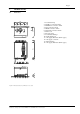
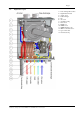
Page 2 2 TECHNICAL DATA 2.
Page 3 2.
Page 4 2.3 Technical data General EC product ID number Dimensions (HxWxD) Category Type of appliance CH water content of appliance CH water content of tap water heat exchanger Weight (empty) CH supply/return connections Gas connections Domestic water, hot/cold Flue connection Air supply Concentric Power consumption Power consumption, partial heat input Power consumption, standby IP-classification Central heating Nominal Heat Input (net) Nominal Heat Input (gross) Max.
Page 5 2.4 Introduction This Installation and Operating manual is for the installer and the user of the ETHOS boiler. It contains essential information for installing and adjusting ETHOS boilers. We recommend that you first consult this installation manual, to ensure that the installation is carried out correctly.
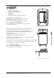
Page 6 3 INSTALLATION 246 246 552 3.1 Unpacking This appliance is supplied with: • Installation and Operating manual; • a user manual with warranty card; • a bleed key; • a hanging bracket; • Condensation trap with condensate discharge hose. Check the appliance immediately on receipt. Any damages must be reported to the supplier immediately. All appliances are completely assembled. Ethos combination boilers are adapted to natural gas G20 3.
Page 7 3.4 Flue System General Air supply material: PP plastic or stainless steel Flue discharge material: plastic (temperature resistant up to 120° C, air flushed) or stainless steel Attention! First connect all pipes and fill up and bleed the installation before commissioning the boiler. The high flue gas temperature protection for plastic discharge material is built into the boiler as a safety feature.
Page 8 3.7 Class B23 C13 C33 C43 C53 Classification according to evacuation of combustion products System description • Non-room sealed application; flue connected to outside but combustion air is being drawn directly from room where boiler is installed.
Page 9 3.8 Ethos resistance table By using different flue installations, either concentric or the 2 pipe system different flue lengths can be achieved, Up to a resistance of 150 Pa. At this pressure the heat input will be equal (±5%) to the heat input specified on the data plate of the appliance. In case a concentric system is used, its length should not exceed 12 meters.
Page 10 3.9 Condensate discharge The condensate discharge must be installed during the assembly. Install the condensate discharge as follows: Slide the supplied cup bottle trap over the two condensate hoses under the boiler, so the arrows are facing each other. Then push the cup against the bottom of the boiler. Turn the trap in position until the condensate discharge faces the desired direction. Attach the condensate discharge hose to the trap with a plastic swivel and seal.
Page 11 3.11 Pump circuit Depending on the boiler version, several types of pumps can be found inside the appliance; a built-in Grundfos UPS 15-60 HB pump or a Grundfos UPS 15-70 HB pump (Ethos 54C only). 3.11.1 On/off pump The pump has a speed switch which is factory-adjusted to the highest position. Attention! The pump speed should not be adjusted Position Ι ΙΙ ΙΙΙ Ethos 36C X Right Right Ethos 54C X X Right The appliance has a built-in pump overrun timer. 3.
Page 12 4 ASSEMBLY INSTRUCTIONS FOR ELECTRICIAN 4.1 Mains connection The boiler requires an earthed 230 volt 50 Hz single phase supply and must be connected in accordance with all current regulations and requirements. A permanent supply to the boiler is needed at all times to the boiler, which should be protected by a maximum 3 Amp double-poled isolator with at least 3mm of contact separation on both poles.
Page 13 4.
Page 14 5 OPERATION 5.1 Display The display has two digits, which indicate the supply temperature of the central heating water in the boiler: By pressing the Info button, the operating status can be displayed. If the Info button is pressed twice, the display will show the water temperature of the central heating water. If the display shows a code that starts with a (t), the boiler will temporarily shut down, except for code t4 and t5. If these are active, the boiler will run an emergency programme.
Page 15 2. Installer menu: Perform the following actions to access the Installer menu. Ø First press the ’-’ and ’Info’ buttons simultaneously (3 sec.). Ø After pressing these buttons, the window will show a ’0’. Ø Then enter code ’8’ by using the ’+’ or ’-’ buttons and press the Info button to access the Installer menu (see 5.4 Installer programme). Ø Exit this Installer menu by pressing the Info button until the display shows the central heating water temperature.
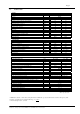
Page 16 Table 5 Resistance table for sensors Resistance Resistance Temperature sensor Temperature [°C] 10K NTC [°C] [Ohm] sensor 12K NTC (outside temperature sensor) [Ohm] 0 32550 -30 171800 5 25340 -25 129800 10 19870 -20 98930 15 15700 -15 76020 20 12490 -10 58880 25 10000 -5 45950 30 8059 0 36130 35 6535 5 28600 40 5330 10 22800 45 4372 15 18300 50 3605 20 14770 55 2989 25 12000 60 2490 30 9804 65 2084 35 8054 70 1753 40 6652 75 1481
Page 17 5.4 Installer programme If the installer code is entered (after pressing the ’-’ and ’Info’ buttons for 3 sec.), the following parameters can be set or modified (modify by using the ’+’ and ’–’ buttons). See table 7. After modifying the parameters, you can exit this programme by pressing the ’Info’ button (3 sec.). The modified settings will be saved automatically. 5.5 Explanation of options for installer 5.5.1 Programme number J1: Max. CH supply temperature This option is used to set the max.
Page 18 Programme number Programme description Setting range Default setting *J1 *J2 *J3 Installer code Max. CH supply temperature Max. CH heat output Pump operation Installer code is 8 85°C 80% 0 *J4 *J5 *J6 Pump overrun time for CH mode Pump overrun time for DHW mode Step modulation *J7 *J8 DHW temperature Max. DHW heat output 0 – 99 10°C – 90°C 30% en 99% 0 = pump overrun time active 1 = pomp continuous 0…30 min. 0…30 min..
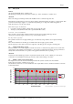
Page 19 5.5.8 Programme number J8: Max. DHW output This parameter enables you to adjust the heat output for DHW. 99% 95% 90% 85% 80% 75% 70% 65% 60% 55% 50% 45% 40% 35% 30% Ethos 36C kW 36 34 32 31 29 27 25 23 22 20 18 16 14 13 11 Ethos 54C kW 54 51 49 46 43 41 38 35 32 30 27 24 22 19 16 1. An OpenTherm® clock thermostat with a built-in outside temperature control and outside temperature sensor** Connect the OpenTherm® thermostat to terminals 1 and 2 of the terminal block in the boiler.
Page 20 programme is started when the power supply is switched on for the first time or when pressing the Info button after a failure. This start-up programme takes 2 minutes: the display shows code ’t8’. After the bleeding programme has finished, the boiler will start to operate. DHW circuit The cold and hot tap water connections are located at the bottom of the appliance. Connect the pipes according to statutory regulations. Adjust the built-in water flow rate restrictor cock (No. 11, 2.
Page 21 5.7 Starting the appliance 5.7.1 General The initial pressure in the gas pipe can be measured with the gas control valve measuring nipple (3). The minimum initial pressure for the proper operation of the appliance must be 10 mbar. 5.7.2 First commissioning When you have tested the installation and everything is in order, you can insert the plug of the central-heating boiler's mains cord into the wall socket.
Page 22 5.8.4 Min. input setting After setting the max. input, press the ’–’ button. The display alternately shows the lower position min. speed which is 1.5 or 1.7 (= 1,500 rpm Ethos 36C and 1,650 rpm Ethos 54C), depending on the applied type, and an ’L’. Turn the screw [1] for the min. setting to adjust this min. input. Note: When adjusting the CO2 percentage, turn the adjusting screw only slightly.
Page 23 6 FAILURES There are a number of situations during which the appliance will shut down due to a failure and can only be activated again by pressing the Info button. Failures are indicated by a flashing dot behind the water temperature in the lower right side corner of the display. By pressing the Info button, the failure will be shown briefly and the boiler will automatically start operating again. The following 'lock-out' failures can occur.
Page 24 In addition, there are a number of failures or problems which cannot be shown on the display. Below a number of these failures or problems are listed: Table 10 Other types of failures Symptom a b c d e f g h i j k l 6.
Page 25 35. 36. Ignition electrode defective (porcelain cracked); wrong distance to burner Moisture on gas valve cables or ignition cable. 37. 38. 39. 40. 41. 42. 43. 44. 45 46 47 Moisture on printed circuit board in burner control unit. Moisture in pump wiring. Moisture in fan or connection. Fan plug not connected properly. Mains plug not connected properly. Connecting cable damaged. Sensor defective. Flue re-circulation at the back of the heat exchanger.
Page 26 6.2 Table of solutions Table 12 Solutions to failures 1. 2. 3. 4. 5. 6. 7. 8. 9. 10. 11. 12. 13. 14. 15. 16. 17. 18. 19. 20. 21. 22. 23. 24. 25. 26. 27. 28. 29. 30. 31. 34. 35. 36. 37. 38. 39. Check or replace the cable; check the connection on the terminal block. Replace room thermostat or cable: check if the proper thermostat is installed. Replace sensor or locate error in cable. Try to loosen the pump shaft or replace pump drive.
Page 27 40. 41. 42. 43. 44. 45 46 47 48 49 50 51 52 53 54 55 56 57 58 59 60 61 62 63 64 65 66 67 68 Plug/wire connection should point toward the outside of the fan and fall into the PCB groove on one side. Check plugs and make sure that they are pressed together properly. Check if the cables are damaged or jammed and replace, if necessary. Check pipe connections, replace sensor. Check heat exchanger seal on flue box, reinstall if necessary, install new lip ring.
Page 28 7 MAINTENANCE 7.1 General Maintenance tasks / inspections must be performed by a registered installer or gas service company, if: 1. The appliance generates a number of similar error codes. 2. A max. interval of 12 months has expired after installation or last inspection/maintenance. ATTENTION: High Voltage Before opening the boiler casing for maintenance or servicing parts, the 230VAC main supply to the boiler must be disconnected! 7.
Page 29 7.3 Maintenance Depending on the inspection results, maintenance or preventive maintenance must be performed. Reasons for maintenance are: ad. a Comments or complaints from the client about the operation of the central-heating boiler can reveal possible hidden defects or problems. ad. b The installation pressure must be between 1 and 2 bar: locate possible leaks in the installation which must be repaired by an installer or service department. ad. c Possible leaks must be repaired. ad.
Page 30 8 USER INSTRUCTIONS Instructing the user: Show the user how to operate the boiler and the installation. It is especially important to familiarise him or her with the safety equipment. Tell the user that the central-heating boiler requires a service inspection/maintenance at no more than 12 months intervals from installation. A periodic service is essential for the safe operation of the central-heating boiler. Give the user the documentation supplied with the central-heating boiler.
Page 31 9 EXPLODED VIEW Installation and Operation manual ETHOS 36C and ETHOS 54C –1511/05-issue1
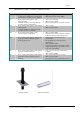
Page 32 10 PARTS LIST Table 13, Spare parts Pos Description No. Mounting bracket 1 Rear panel 2 Cable gland Air supply seal 8o mm Side panel incl. insulation Front panel, complete Front panel lid incl. hinge Flue pipe 80 mm Flue pipe gasket 80mm 3 4 5 6 Order No.
Page 33 Declaration of conformity according to the EC Machine DIRECTIVE (89/392/EEG, 91/386/EEG, 93.68/EEG) and the EC EMC DIRECTIVE (89/336/EEG, 91/263/EEG, 92/31/EEG, 93/68/EEG) Itho bv in Schiedam, the Netherlands Hereby declares that its central-heating boilers: Name: Ethos Type: 36C, 54C are built in accordance with the applicable provisions in the EC Machine DIRECTIVES and the EC EMC DIRECTIVE. Yours sincerely, W.