
Installation Guide


8
Hook Mounting (continued)
4
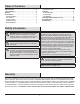
Making the electrical connections
□ Run the power cable and dimming cable from the fixture body (A) to the electrical
outlet box, feeding the wires through the two waterproof connectors (FF).
□ Insert the waterproof connectors (FF) into the electrical outlet box.
□ Attach the power cable and the dimming cable from the fixture body (A) to the
chain with a cable tie (not included).
□ Connect the hot and neutral (black and white) wires from the fixture body (A) to
the same color wires in the electrical box.
□ Connect the green wire from the fixture body (A) to the ground wire in the
electrical box.
□ If a 0-10v dimming circuit is available, connect the purple and gray wires from
the fixture body (A) to the same color wires in the electrical box.
□ If 0-10v dimming is not desired, wrap the ends of the purple and gray wires with
electrical tape to cover the wire.
□ Cover the wire connections using the wire connectors (GG).
□ Wrap the wire connectors (GG) with electrical tape for a more secure connection.
□ Tuck all electrical connections into the electrical outlet box.
Yoke Mounting
5
Completing the installation
□ Cover the electrical outlet box.
□ Restore power at the electrical panel.
□ Turn on the light switch to activate the fixture.
MM
LL
AA
FF
GG
1
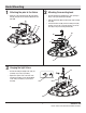
Marking the yoke position
□ Place the yoke mounting bracket (AA) in the desired
position and mark the location of the mounting holes with
a pencil.
□ Drill 3/8 inch pilot holes in the marked locations.
□ Place drywall anchors (MM) into the 2 pilot holes.
□ Mount the yoke mounting bracket (AA) by tightening
the two mounting screws (LL) securely into the drywall
anchors (MM).