E-TON VIPER OWNER’S MANUAL Viper 50M, Viper 70, Viper 90 and Viper 90R
Important Notices READ and UNDERSTAND this owner’s manual Both the operator and the adult supervisor should completely read and understand this owner’s manual before operating this vehicle. This owner’s manual will instruct you in the safe operation of the vehicle. NO Passengers This vehicle was designed for operation ONLY by the operator, (Driver). The load limit and seat configuration is designed for the operator ONLY. It is not safe to carry passengers on the vehicle.
Table of Contents Safety notes Vehicle identification number location Controls, switches and feature locations Control feature operations Engine stop switch Manual Choke Lever Throttle lever Front & Rear Brakes Parking brake Safety Tether Switch Remote Stop / Start Switch Fuel System Fuel tank Fuel valve Inline Fuel Filter Engine Oil Oil Tank Oil Indicator light Tires & Wheels Tire inspection Tire pressure Spark Plug Spark Arrester Screen Air Filter Braking Systems Front Brake Inspection Front Brake Adjustm
Specifications Viper 50M Viper 70 Viper 90 & 90R Maintenance Schedule Maintenance Record Chart Wiring Diagram Viper 50M Wiring Diagram Viper 70 Wiring Diagram Viper 90 Wiring Diagram Viper 90R Manufacture’s Warranty Owner’s Notes Page 3 22 24 26 28 28 29 30 31 32 33 35
Safety Notes 1. Both the adult supervisor and youth operator must fully understand everything in this manual before operating this vehicle. 2. This vehicle was designed for the operator only. NO PASSENGERS should be allowed on this vehicle. 3. This vehicle is designed for operation on level, obstacle free off-road areas. 4. Riding this vehicle on public roads or highways is illegal. If it becomes necessary to cross a public road or highway, the vehicle should be pushed across using extreme caution. 5.
10. NEVER ride this vehicle unless it has been properly maintained and adjusted. Always perform a pre-ride inspection of your vehicle. Look for wires, bolts and other fasteners that may have come loose on previous rides. Inspect the drive chain, throttle and brakes for proper adjustment and operation. Check the engine oil level in the oil tank. Check fuel level and inspect for fuel leaks. (Remember, you can ride further in 1 hour than you can walk back in 1 day!) 11.
13. NEVER REFUEL this vehicle when hot. Ask your adult supervisor to refuel your vehicle. Gasoline is extremely flammable and will ignite if spilled on a hot engine or muffler. Never smoke or expose the fuel to an open flame or spark while refueling your vehicle. Always refuel your vehicle in a safe place free of any ignition source. 14. NEVER run the vehicle in an enclosed area.
Additional safety tips: • • • • • • • • • • • • • • • • • • • • • • • • • • • Participate in an approved ATV safety education training program Always provide responsible adult supervision for ATV operators younger than 18 years of age Don't let youngsters ride full-sized ATV's Follow all safety recommendations of the ATV manufacturer Operate ATVs only during daylight Wear a helmet with face protection at all times Operate only four-wheeled ATVs Provide a drug and alcohol free environment Always use the b
Vehicle Identification Numbers Vehicle Identification Number (VIN) is located at the front of the unit under the front fender on a plate mounted between the main frame rails. Engine serial number is located on the left-hand side of the engine on the crankcase housing. Your VIN RFZ______________ Eng. No._______________ Controls, Switches & Feature Locations Locations of controls and features 1. Fuel Tank filler and vent tube 2. Front brake lever (Parking Brake Lock) 3. Throttle lever 4.
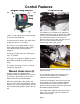
Control Features Throttle lever Engine Stop Switch The stop switch is a red colored rocker switch located on the left-hand handle bar. To start and run the engine, this switch must be placed in the on, “O”, position. The throttle lever is located on the right-hand handle bar below the grip. To operate the throttle lever, place your right thumb on the lever and press forward to increase your speed.
Front and Rear Brakes This vehicle is equipped with dual front mechanical drum brakes and a rear hydraulic disc brake. (Viper 70 Viper 90 & Viper 90R) (Viper 50M is equipped with rear hydraulic disc brake only) If your engine fails to start, ensure that the engine stop switch is in the on, “O”, position and that the parking brake is engaged. Safety Tether Switch The front brakes are controlled by the long brake lever on the right-handle bar.
Once the unit has been stopped with the remote switch you must press the run button in order for the unit to be restarted. This action resets the remote receiver on the unit. dirt or other debris to enter the tank when refueling. Replace the cap if damaged or if it will not seal to the tank. The unit may also be started remotely by pressing both the Stop & Run buttons together. Tighten the cap snugly, being careful not to over tighten. Over tightening the cap can cause damage to the cap or seal.
reserve in the tank to allow the unit to be taken to a refueling location. abrasions and deterioration. Replace fuel lines as needed. When you have to switch to the “RES” position you must refuel the unit as soon as possible. DO NOT start or operate the engine if the fuel filter or lines are leaking. Leaking fuel can cause a fire. ALWAYS CHECK YOUR Fuel level before you start riding your ATV. Remember: You can drive further in one hour on your ATV than you can walk in one day.
The unit is also equipped with an oil level indicator lamp. The lamp will light when the oil level in the tank is low. When the lamp is lit you MUST refill the oil tank. DO NOT allow the engine to operate with an empty oil tank. Doing so will result in extensive damage to your engine. This damage is not covered under the warranty. Check the oil tank level manually during every other refueling operation. The oil tank capacity is 1.1 liters, 1.2qt.
3. After every 200 hours of operation the Spark Arrester has to be replaced by loosening the retaining nut using a 10mm socket or wrench. Using pliers turn the sleeve of the Spark Arrester counterclockwise and pull out. Replace a new Spark Arrester and secure it by tightening the retaining nut. Air Filter Wash the element in a non-flammable solvent such as Air-Filter cleaner from your local auto parts dealer. 1. Dry the element completely before continuing. 2.
DO NOT RIDE A UNIT WITH WORN BRAKE SHOES. Replacement of the brake shoes and cables Test the brakes by applying pressure to the brake lever and trying to push the unit forward. If the wheel rotates while the brakes are applied, adjust the brake cable until the wheels no longer rotate. (See Brake Adjustment) Brake Adjustment should ONLY be preformed by a qualified mechanic. Rear Brake System Inspection Visually inspect the brake hose for any signs of wear or leaks.
To Fill the Reservoir Remove the reservoir cover by removing the two cover bolts. Fill the reservoir to 1/8” from top with Dot-3 SAEJ1703 grade brake fluid. Purging Brake Lines For the hydraulic brake system to operate safely, the brake system must be purged of air in the lines and reservoir. To bleed the air will require two people to perform the following procedure. Caution: DO NOT allow dirt to fall into the reservoir. Refold the cover gasket as shown in picture and replace cover and bolts 1.
Drive Chain The drive chain will stretch with use and will require periodic adjustments. To check the chain tension, remove the chain guard and measure the slack. The amount of slack in the chain should not exceed 10-20mm or ¼” - ½”. Inspect the drive and axle sprockets for worn, damaged or broken teeth. Replace as needed. Inspect the chain links for damaged, worn or loose rivets. Repair or replace as needed.
Loosen the throttle stop screw locking nut and turn the throttle stop screw clockwise to reduce the battery to full charge before replacing it in the unit. When reinstalling the battery, be sure to connect the red cable to the positive (+) terminal and the black cable to the negative (-) terminal. The battery should be replaced every three years or when it no longer holds a charge. the throttle travel thus reducing the maximum speed of the unit.
Transmission Gear selector Viper 90R (only) The Viper 90R model is equiped with a transmission gear selector switch mounted on the right hand side of the handlebars. The switch has three positions (“R” “N” “F”). “R” = Reverse “N” = Neutral “F” = Forward ATV Break In procedures Your ATV requires a break in period just as with all other internal combustion engines. This period allows the engine parts to seat and wear properly without undue strain which can cause premature failure. 1.
4. Allow the oil to drain completely (15-30 min). 5. Reinstall the drain plug and tighten. Torque to 7-10lbf-ft 6. Fill the transmission box with SAE 8090 gear oil. a. V70 & V90 100cc / 3.4oz b. V90R 300cc / 10.2oz 7. Reinstall the fill hole plug finger tight. 8. Dispose of used oil at a proper recycling station as required by law. Pre-Operation Inspection procedure The following procedure must be performed before each operating session.
Start your ATV by following the starting procedure above and allow the engine a few minutes to warm up before releasing the parking brake. Start the unit by slowly increasing the throttle until the unit begins moving. Turning your ATV Learning to turn your ATV requires you to learn to shift your weight and control the throttle to allow the rear wheels to turn properly.
2005 VIPER 50M ATV Specifications Viper 50M (RXL-50M) Engine Type Displacement Bore / Stroke Compression Power Two cycle air cooled 49.3cc φ40.0 * 39.2mm 6.8 : 1 5.2ps @ 7000rpm Transmission Type Automatic (C.V.T. V-Belt) Chassis Overall Length Overall Width Overall High Wheel Base Dry Weight 1430mm / 56.3" 820mm / 32.3" 800mm / 31.5" 930mm / 36.
Tires Front Rear Front Min Max Rear Min Max Tire Pressure 145/70-6 145/70-6 2psi / 0.14kg/cm2 (Cold) 7psi / 0.49kg/cm2 (Cold) 2psi / 0.14kg/cm2 (Cold) 7psi / 0.
2005 VIPER 70 ATV Specifications Viper 70 (RXL-70) Engine Type Displacement Bore / Stroke Compression Power Two cycle air cooled 68.0cc φ47.0 * 39.2mm 8.3 : 1 6.3ps @ 6000rpm Transmission Type Automatic (C.V.T. V-Belt) Chassis Overall Length Overall Width Overall High Wheel Base Dry Weight 1470mm / 57.9" 850mm / 33.5" 830mm / 32.7" 930mm / 36.
Tires Front Rear 16/8-7 16/8-7 Front Min Max Rear Min Max Tire Pressure 2psi / 0.14kg/cm2 (Cold) 7psi / 0.49kg/cm2 (Cold) 2psi / 0.14kg/cm2 (Cold) 7psi / 0.
Viper 90 & Viper 90R ATV Specifications Viper 90 (RXL-90) & Viper 90R (RXL-90R) Engine Type Displacement Bore / Stroke Compression Power Two cycle air cooled 82.5cc φ50.0 * 42.0mm 5.8 : 1 7ps @ 7500rpm Transmission Type Automatic (C.V.T. V-Belt) Chassis Overall Length Overall Width Overall High Wheel Base Dry Weight 1500mm / 59.0" 850mm / 33.5" 900mm / 35.4 930mm / 36.
Tires Front Rear Front Min Max Rear Min Max Tire Pressure 18/7-8 18/9-8 2psi / 0.14kg/cm2 (Cold) 7psi / 0.49kg/cm2 (Cold) 2psi / 0.14kg/cm2 (Cold) 7psi / 0.
Maintenance Schedule First week Every 30 Days Every Year I Fuel Lines Throttle Operation Air Filter Fuel Filter Spark Plug Drive Chain Brake Shoes Brake System I I C I, L I Inspect as part of pre-ride inspection I Inspect as part of pre-ride inspection I Brake Fluid Bolts, Nuts & Fasteners Wheels Replace Fuel & Vent Lines every 2 years Inspect as part of pre-ride inspection R R R I I, L I I Notes I I I I I Steering system Every 6 months Suspension System C.V.T. Filter C.V.T.
Wire diagram Viper 50M (RXL-50M) Page 29
Diagram Viper 70 (RXL-70) Page 30
Wire Diagram Viper 90 (RXL-90) Page 31
Wire diagram RXL-90R Page 32
ETON AMERICA, LLC. LIMITED VEHICLE WARRANTY ETON America warrants all new ETON vehicles sold by authorized Eton Dealers to be free from defects in materials and workmanship, subject to the following exclusions and limitations. New vehicles sold by an authorized dealer to original retail consumers are covered by this policy for a period of six (6) months from the date of delivery. There is no mileage limitation.
ETON AMERICA, LLC. LIMITED VEHICLE WARRANTY Scheduled maintenance service is the responsibility of the owner during and after the warranty period. In the event of a failure or required repair, the owner should take vehicle to an authorized dealer for repair without undue delay and within a maximum of thirty, (30), days of the occurrence of the problem. All eligible warranty repairs must be made at any authorized dealer’s normal place of business.
Owner’s Notes: Page 35
Owner’s Notes: Page 36
Owner’s Notes: Page 37
Owner’s Notes: Page 38
Page 39