Archived 3/18/10 Model 2080/2081 Turntable Series MANUAL 1.2 m / 1.5 m © ETS-LINDGREN L.P.
Archived 3/18/10 MODEL 2080 / 2081 TURNTABLE SERIES ETS-Lindgren L.P. reserves the right to make changes to any products herein to improve functioning, design, or for any other reason. Nothing contained herein shall constitute ETS-Lindgren L.P. assuming any liability whatsoever arising out of the application or use of any product or circuit described herein. ETSLindgren L.P. does not convey any license under its patent rights or the rights of others. © Copyright 2003 by ETS-Lindgren L.P.
Archived 3/18/10 MODEL 2080 / 2081 TURNTABLE SERIES Table of Contents INTRODUCTION ........................................................................................................................................ 1 STANDARD CONFIGURATION .............................................................................................................. 2 OPTIONS ................................................................................................................................................
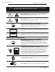
Archived 3/18/10 NOTICE: MODEL 2080 / 2081 TURNTABLE SERIES This product and related documentation must be reviewed for familiarization with safety markings and instructions before operation. SAFETY SYMBOL DEFINITIONS ! REFER TO MANUAL When product is marked with this symbol refer to instruction manual for additional information. OR HIGH VOLTAGE Indicates presence of hazardous voltage. Unsafe practice could result in severe personal injury or death.
Archived 3/18/10 MODEL 2080 / 2081 TURNTABLE SERIES Introduction INTRODUCTION The ETS-Lindgren Model 2080/2081 Turntable Series is a family of electric powered turntable platform systems designed to be used with the Model 2090 Positioning Controller for EMI compliance testing. The primary difference between the Model 2080 and 2081 is the turntable top surface. The Model 2080 series turntables are equipped with a rugged textured ABS surface laminated to a PVC plate.
Archived 3/18/10 Standard Configuration MODEL 2080 / 2081 TURNTABLE SERIES The Model 2080 and 2081 are designed for indoor/outdoor applications, provided adequate drainage is available for outdoor installations. Drainage considerations are covered in the installation section of this manual. While the units are indoor/outdoor capable, they may not be suitable for outdoor conditions with extreme temperatures or high humidity. STANDARD CONFIGURATION Model 2080 1.2 and 1.
Archived 3/18/10 MODEL 2080 / 2081 TURNTABLE SERIES Options OPTIONS 2080 Model 2090 Positioning Controller: This controller provides 2081 control for two separate devices (towers and turntables) in any combination, plus the control of four auxiliary devices via a fiber optic interface. The unit includes a GPIB connection and is compatible with most popular EMI measurement software.
Archived 3/18/10 Precautions MODEL 2080 / 2081 TURNTABLE SERIES PRECAUTIONS Read this manual completely before starting installation. This equipment should be installed and operated only by qualified personnel. Ensure that the correct voltage setting is selected on the Motor Base unit. The fiber optic cable must be looped through the “P” clip installed on the front panel of the motor base.
Archived 3/18/10 MODEL 2080 / 2081 TURNTABLE SERIES Turntable Installation Considerations TURNTABLE INSTALLATION CONSIDERATIONS Pre-planning is essential for a successful installation. Be sure to discuss your requirements with your sales representative and request dimensional drawings prior to construction of your site. POWER AND SIGNAL LINES Conduit Power and signal line paths should be planned in advance. Conduit should be in place before pouring concrete or installing the ground plane.
Archived 3/18/10 Turntable Installation Instructions MODEL 2080 / 2081 TURNTABLE SERIES TURNTABLE INSTALLATION INSTRUCTIONS GLOSSARY Anchor Plate – Anchors the turntable to the floor and provides an interface for leveling screws. Leveling Screws – (½-13x5” square head screws with ½-13 flangenuts) work in concert to level the turntable assembly. The screws are shipped inserted into the turntable base.
Archived 3/18/10 MODEL 2080 / 2081 TURNTABLE SERIES Turntable Installation Instructions GUIDELINES Proper installation of the turntable directly affects performance. While the Model 2080 and 2081 turntables are shipped fully assembled, there are additional parts for installing the turntable.
Archived 3/18/10 Turntable Installation Instructions MODEL 2080 / 2081 TURNTABLE SERIES TOOLS REQUIRED 3/16” allen wrench 5/16” allen wrench 3/8” allen wrenches, qty 3 6 m.m. allen wrench 3/8” ratchet wrench 12” crescent wrench 15 m.m. 12 point socket for ½” square head screws 7/16” open/box end wrench ½” open/box end wrench ¾” open/box end wrench .
Archived 3/18/10 MODEL 2080 / 2081 TURNTABLE SERIES Turntable Installation Instructions INSTALLATION During the installation process please refer to the drawings at the back of this manual. 1. If the turntable is to be installed in a pit, check the pit depth and inside diameter and compare measurements to the site drawings. Inside pit dimensions are typically as follows: Model 2080 1.21 meter = 49.65” 1.51 meter = 61.46” Model 2081 1.23 meter = 50.44” 1.53 meter = 62.
Archived 3/18/10 Turntable Installation Instructions MODEL 2080 / 2081 TURNTABLE SERIES mark around the perimeter of the turntable base. These marks may be used for reference if the assembly is moved during placement of the floor shims or anchor plates. When positioning the turntable base, make as many anchor holes miss the floor joint strips as possible if the table is being installed on a panel floor in a chamber. 6. The hardware kit contains 12 floor plates.
Archived 3/18/10 MODEL 2080 / 2081 TURNTABLE SERIES Turntable Installation Instructions 11. While the ½-13x5 square head screws are all identical, they serve two purposes. The screws installed in step 9 anchor the assembly through the anchor plates and into the floor. The screws you are about to manipulate will level the assembly with the raised floor or ground plane. Please refer to the drawings at the back of this manual to determine which screws serve each purpose.
Archived 3/18/10 Turntable Installation Instructions MODEL 2080 / 2081 TURNTABLE SERIES 2081 RAISED PANEL FLOOR FLANGE INSTALLATION For this step you will need: pipe clamp three 3/8” allen wrenches hand drill 5/32” drill bit #3 phillips drive bit a small square marker ¼”x 1-3/4” phillips flat head TAPCON screws hacksaw 1.2 and 1.5 meter turntables with the floor flange option have two floor flange pieces.
Archived 3/18/10 MODEL 2080 / 2081 TURNTABLE SERIES Turntable Installation Instructions have more than 1/16" gap between the butt joint when finished. Continue mounting as stated above until all screws have been installed. Also the top floor joint strips will need to be trimmed to fit up against the flange. 2081 INSTALLATION OF STAINLESS STEEL WEAR STRIP Tools and Hardware Needed: eight small 1-1/2” C-clamps 6-32x 3/8” thread rolling screws hand drill 0.120 dia.
Archived 3/18/10 Turntable Installation Instructions MODEL 2080 / 2081 TURNTABLE SERIES fixed end. The gap of the 2 joints should be less than 1/16”. Deburr the cut. You will need to drill the last hole about the same distance as the other end. Greasing Casters & Bearings: Using a synthetic grease, grease all casters. Mobil 1 synthetic is recommended, do not use a lithium grease. NOTE: Some casters may not have grease fittings. These will be sealed bearings and will not require grease.
Archived 3/18/10 MODEL 2080 / 2081 TURNTABLE SERIES Turntable Installation Instructions 2081 ROLLED STEEL FLANGE MOUNTING IN CONCRETE PIT Mounting to concrete is the same with the exception of the mounting hardware. You should have ½-13 wedge type concrete anchors. Instead of the #14 x 1” square socket flat head screws, you will use 1/4 x 1-3/4 Phillips flat head TAPCON screws. You will need a ½” hammer drill with a ½” x 12” hammer drill bit and a 3/16 x 6” hammer drill bit.
Archived 3/18/10 Turntable Installation Instructions MODEL 2080 / 2081 TURNTABLE SERIES FINAL HEIGHT ADJUSTMENT Once the table has been pre leveled, floor flanges mounted, and the wear strips mounted, you are now ready to finish leveling. Rotate table to where the joint of the table top is directly over the center of the caster. Making sure not to get caster out of level from side to side, slowly raise caster until table top is about 1/32” above the highest spot on the floor flange.
Archived 3/18/10 MODEL 2080 / 2081 TURNTABLE SERIES Turntable Installation Instructions will lead to high voltage drop in the power conductors and cause reduced starting torque and premature motor failure. Connect the fiber optic control cable and install the power connection according to the “Electrical Installation” section. The fiber optic cable must be looped through the “P” clip installed on the front panel.
Archived 3/18/10 Turntable Installation Instructions MODEL 2080 / 2081 TURNTABLE SERIES WARNING Ensure the current travel limit settings will not cause damage to existing cables and equipment located underneath the turntable. Once limits have been set, return the turntable to its original position and replace the top section. 18 © ETS-LINDGREN L.P.
Archived 3/18/10 MODEL 2080 / 2081 TURNTABLE SERIES Electrical Installation ELECTRICAL INSTALLATION It is important that this electrical installation CAUTION procedure be performed by a qualified electrician, in accordance with local and national electrical standards prior to energizing the unit. CAUTION Ensure power is off and secured before proceeding further. The voltage select switch on the Motor Base Unit must be set to the proper mains voltage before power is applied to the unit.
Archived 3/18/10 Electrical Installation MODEL 2080 / 2081 TURNTABLE SERIES CONNECTING THE MODEL 2090 POSITIONING CONTROLLER Any combination of primary devices (towers, turntables, reverberation paddles, MAPS, etc.) can be connected to the two Device Interface ports located on the rear panel of the Model 2090 controller. For easy set up of an EMC facility, it is recommended that the turntable be connected to the Device 2 interface port.
Archived 3/18/10 MODEL 2080 / 2081 TURNTABLE SERIES Operation turntable is attached to the motorbase and it is time to set the rotation limits for the turntable. Disconnect the power for the Model 2090 and the motor base before proceeding with the assembly of the turntable. Disconnect the fiber optic cables from the units so they will not be damaged during installation. CAUTION The limits must be set whether or not the soft limits in the 2090 controller are used.
Archived 3/18/10 Operation MODEL 2080 / 2081 TURNTABLE SERIES RECOMMENDED PARAMETERS FOR THE MODEL 2090 POSITIONING CONTROLLER Parameter P1 P2 P3 P5 P8 P9 b1 c S0 S1 S2 S3 S4 S5 S6 S7 S8 Oc Value 0 0 000 1 2.5 9 000 3600 -1 31 63 95 127 159 191 223 255 On DEVICE 2 Description Turntable Standard Turntable Infinite Scan Count Non-continuous rotation 2.5 Second reverse delay Primary GPIB address 9 User options disabled 3600 encoder counts per meter Step speed = run speed Speed 1 ~12.
Archived 3/18/10 MODEL 2080 / 2081 TURNTABLE SERIES Operation selection. Pressing any of the remaining motion keys will return the display to the current position and execute that motion. Pressing the PARAM key again will return to the last displayed parameter in the list, allowing easy transition between parameter adjustment and device operation. Once the desired limit, position or parameter is visible in the display window, pressing INCRM, DECRM, or ENTER will toggle into edit mode.
Archived 3/18/10 Operation MODEL 2080 / 2081 TURNTABLE SERIES 5. Record the reading of the display, ignoring the decimal point (i.e. 360.0 would be 3600). This is the encoder calibration value. NOTE: If the value is below 3600, the resolution of the encoder is low and thus the 2090 will not provide 0.1 degree resolution, even though the display shows that digit. If the value has gone past 9999, the encoder has too many counts per meter and the 2090 can not correct for it.
Archived 3/18/10 MODEL 2080 / 2081 TURNTABLE SERIES Operation The table is rotated from 0 to 360 and the mark is now within one degree of being one full TT revolution. Calibration is complete. © ETS-LINDGREN L.P.
Archived 3/18/10 Operation MODEL 2080 / 2081 TURNTABLE SERIES CONTINUOUS ROTATION / DISENGAGING MECHANICAL LIMIT SWITCHES The motor drive unit contains a mechanical limit switch mechanism that is coupled to the encoder shaft inside the drive unit. For continuous rotation it is necessary to disengage the coupling per instructions below. This will then prevent the mechanical limits from being engaged.
Archived 3/18/10 MODEL 2080 / 2081 TURNTABLE SERIES Operation SETTING CURRENT POSITION ON 2090 The total travel between the mechanical limits is between 370 and 400 degrees. This is fixed by the engagement mechanism inside the drive unit and is non-adjustable. Set the 0 degree position on the 2090 so that the 2090 moves the table between the mechanical limits without engaging them in normal operation.
Archived 3/18/10 Hand Control Unit MODEL 2080 / 2081 TURNTABLE SERIES HAND CONTROL UNIT To connect the Hand Control Unit (HCU), remove the connector cap on the motor base. Plug the cable receptacle from the hand control unit into the electrical enclosure and screw connectors completely together. The HCU is now ready to operate. Be sure to coordinate use of the unit with the operator of the Model 2090 Positioning Controller. To allow the HCU to operate, push the control switch from MAIN to HAND.
Archived 3/18/10 MODEL 2080 / 2081 TURNTABLE SERIES Maintenance MAINTENANCE Regular maintenance will prolong the serviceability of your turntable. Follow this recommended schedule. CAUTION Do not perform maintenance while turntable is operating. CAUTION: When removing the Model 2081 top use caution. The edges are greasy from the conductive grease and the copper ground brush is very sharp. Use rags or gloves when handling the edges to prevent cuts and abrasions.
Archived 3/18/10 Specifications MODEL 2080 / 2081 TURNTABLE SERIES Grease the gear teeth. Apply good quality grease to the gear teeth. SPECIFICATIONS ELECTRICAL Model Nominal AC Voltage Input Frequency Current Rating Phase RPM 2080 115/230 VAC 50/60 Hz 3.8 / 2.5 A Single (1) 1.3 2081 115/230 VAC 50/60 Hz 4.0 / 3.0 A Single (1) 1.3 MECHANICAL Diameter 1.2 m (48 in) or 1.5 m (59.24 in) Height 26.67 cm (10.5 in) Load Rating 455 kg (1000 lb) distributed 30 © ETS-LINDGREN L.P.
Archived 3/18/10 MODEL 2080 / 2081 TURNTABLE SERIES Warranty Statement WARRANTY STATEMENT ETS-Lindgren L.P., hereinafter referred to as the Seller, warrants that standard EMCO products are free from defect in materials and workmanship for a period of two (2) years from date of shipment.
Archived 3/18/10 Warranty Statement MODEL 2080 / 2081 TURNTABLE SERIES EUROPEAN COMMUNITY DECLARATION OF CONFORMITY The EC Declaration of Conformity is the method by which EMC Test Systems, L.P. declares that the equipment listed on this document complies with the EMC and Low-voltage Directives. Factory: EMC Test Systems, L.P. P.O. Box 80589 Austin, Texas USA 78708-0589 Issued by: EMC Test Systems, L.P. P.O.
Archived 3/18/10 MODEL 2080 / 2081 TURNTABLE SERIES Illustrations ILLUSTRATIONS © ETS-LINDGREN L.P.
Archived 3/18/10 Illustrations 34 MODEL 2080 / 2081 TURNTABLE SERIES © ETS-LINDGREN L.P.
Archived 3/18/10 MODEL 2080 / 2081 TURNTABLE SERIES © ETS-LINDGREN L.P.
Archived 3/18/10 Illustrations 36 MODEL 2080 / 2081 TURNTABLE SERIES © ETS-LINDGREN L.P.
Archived 3/18/10 MODEL 2080 / 2081 TURNTABLE SERIES © ETS-LINDGREN L.P.
Archived 3/18/10 Illustrations 38 MODEL 2080 / 2081 TURNTABLE SERIES © ETS-LINDGREN L.P.
Archived 3/18/10 MODEL 2080 / 2081 TURNTABLE SERIES © ETS-LINDGREN L.P.
Archived 3/18/10 Illustrations 40 MODEL 2080 / 2081 TURNTABLE SERIES © ETS-LINDGREN L.P.
Archived 3/18/10 MODEL 2080 / 2081 TURNTABLE SERIES © ETS-LINDGREN L.P.