
Instruction manual


Model 2090 Multi-Device Controller
2. all power and cables from the Model 2090
and move it to an open work area.
3.
4.
5.
out of its
socket with a gentle rocking motion. It is not
6. e, gently
remove the two EPROMs, U1 and U5, out of their
slightly and insert the device completely
under the chip to the other end. Avoid prying one end
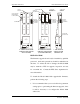
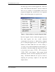
7. oting the orientation of the notch on the flash ROMs,
O bank ROMs, but do not use the
Disconnect
Use an anti-static wrist strap or other suitable ground to
insure that you are properly grounded while you work.
Use a #2 Phillips screwdriver to remove the six screws
(four on top, two along the back top edge) from the lid
of the Model 2090 case. Slide the lid to the back of the
Model 2090 to remove it.
Remove the two mounting screws (if supplied) from the
single board computer and gently lift the SBC
recommended that you attempt to replace the ROM
chips with the SBC installed in the Model 2090.
Using an IC puller or another suitable devic
sockets, taking care not to bend the pins, and place
them on an anti-static pad. Gently pry at both ends, or
pry one end up
all the way out as damage to the IC pins and/or socket
may occur.
N
insert each one oriented as shown in the figure on the
previous page. Refer to the label on the chips to
identify the HI and L
©ETS-Lindgren, April 2006 143
Revision G– P#399199