Archived 3/31/10 Model 2088 EuroPro™ Electric Powered Turntable MANUAL © ETS-LINDGREN L.P.
Archived 3/31/10 MODEL 2088 ELECTRIC POWERED TURNTABLE ETS-Lindgren L.P. reserves the right to make changes to any products herein to improve functioning, design, or for any other reason. Nothing contained herein shall constitute ETS-Lindgren L.P. assuming any liability whatsoever arising out of the application or use of any product or circuit described herein. ETSLindgren L.P. does not convey any license under its patent rights or the rights of others. © Copyright 2003 by ETS-Lindgren L.P.
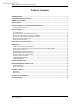
Archived 3/31/10 MODEL 2088 ELECTRIC POWERED TURNTABLE Table of Contents INTRODUCTION ........................................................................................................................................ 1 STANDARD CONFIGURATION .............................................................................................................. 2 MODEL 2088 OPTIONS .............................................................................................................................
Archived 3/31/10 NOTICE: MODEL 2088 ELECTRIC POWERED TURNTABLE This product and related documentation must be reviewed for familiarization with safety markings and instructions before operation. SAFETY SYMBOL DEFINITIONS ! REFER TO MANUAL When product is marked with this symbol refer to instruction manual for additional information. OR HIGH VOLTAGE Indicates presence of hazardous voltage. Unsafe practice could result in severe personal injury or death.
Archived 3/31/10 MODEL 2088 ELECTRIC POWERED TURNTABLE Introduction INTRODUCTION The ETS-Lindgren Model 2088 EuroPro™ is an electric-powered variable-speed turntable platform system designed to be used with the Model 2090 Positioning Controller for EMI compliance testing. The Model 2088 is available in three diameters 1.23 meter, 1.53 meter and 2.03 meter.
Archived 3/31/10 Standard Configuration MODEL 2088 ELECTRIC POWERED TURNTABLE STANDARD CONFIGURATION • • • • • • Turntable Assembly Single-phase electric drive (208-230 VAC 50/60 Hz) Variable speed drive Conductive top Continuous rotation Ten meter fiber-optic control cables (standard) MODEL 2088 OPTIONS Model 2090 Positioning Controller: This controller provides control for two separate devices (EMCO towers and turntables) in any combination, plus the control of four auxiliary devices.
Archived 3/31/10 MODEL 2088 ELECTRIC POWERED TURNTABLE Precautions PRECAUTIONS Read this manual completely before starting installation. This equipment should be installed and operated only by qualified personnel. The electrical installation of this product should be accomplished by an individual who is authorized to so do by the appropriate local authority. The installation should be in compliance with local electrical safety codes. Do not attempt to service unless qualified to do so.
Archived 3/31/10 Turntable Installation Considerations MODEL 2088 ELECTRIC POWERED TURNTABLE TURNTABLE INSTALLATION CONSIDERATIONS Pre-planning is essential for a successful installation. Be sure to discuss your requirements with your sales representative and request dimensional drawings prior to construction of your site. POWER AND SIGNAL LINES Conduit Power and signal line paths should be planned in advance. Conduit should be in place before pouring concrete or installing the ground plane.
Archived 3/31/10 MODEL 2088 ELECTRIC POWERED TURNTABLE Installation INSTALLATION The following instructions are for the installation of 1.23 and 1.53 meter EuroPro turntables. The installation of turntables 2 meters and larger will be performed by a factory installation specialist or by individuals who have been authorized by ETS-Lindgren to do such work. Proper installation of the turntable directly affects performance.
Archived 3/31/10 Installation MODEL 2088 ELECTRIC POWERED TURNTABLE 3/4“ pipe clamp ends 3/4“ pipe (length depends on table size 6 ft. will cover most tables) 1-1/2“ C-clamps, qty 8 Cutting Oil Syringe for applying conductive grease Grease Gun Vacuum Concrete Pit Installations 1/2“ hammer drill 1/2“ x 12 “ masonry bit 3/16" x 6” masonry bit 1/4" x 1-3/4“ Tapcon Screws or equivalent 1. The turntable installation will vary based on the host location.
Archived 3/31/10 MODEL 2088 ELECTRIC POWERED TURNTABLE Installation b. If you have purchased the Integrated Ground Plate Interface option. It should be installed prior to lowering the turntable into place. 5. Remove the bolts which attach the top onto the turntable drive assembly. Refer to the assembly drawing in the rear of this manual for more details. CAUTION Lifting of the turntable assembly using a forklift or other lifting machinery should be performed by qualified personnel. 6.
Archived 3/31/10 Installation MODEL 2088 ELECTRIC POWERED TURNTABLE holes for these screws and vacuum up shavings so that you have good contact with the floor. Continue mounting the rest of the plates. 10. Once all anchor plates are securely mounted, remove the ½-13 x 5” sets screws and then drill 27/64” pilot holes approximately ¾” deep into the paneled floor. Be careful not to penetrate the bottom skin of the panel. Vacuum out shavings and dust.
Archived 3/31/10 MODEL 2088 ELECTRIC POWERED TURNTABLE Installation RAISED PANEL FLOOR FLANGE INSTALLATION The ground ring assembly includes a floor flange which interfaces with the brush ring located on the perimeter of the turntable. The floor flange provides constant electrical contact with the ground plane and is usually installed with the turntable. Mounting methods vary according to user specifications.
Archived 3/31/10 Installation MODEL 2088 ELECTRIC POWERED TURNTABLE Typically the last flange will be too long. Turn the flange upside down, butt one end to the other and evenly mark off with the other end and trim to fit. Do not cut too much off. It is preferable to not have more than 1/16" gap between the butt joint when finished. Continue mounting as stated above until all screws have been installed. Some screws may fall between the floor panel joints.
Archived 3/31/10 MODEL 2088 ELECTRIC POWERED TURNTABLE Installation drill, 0.120 dia. drill bits, a #2 phillips bit, and some cutting oil. Start the strip 1/8" below the surface of the flange at the end with the hole closest to the end of the strip. Also start with the first 2 holes in strip in between the casters. Place a clamp about 2” on either side of the hole on the strip in 4 places and then transfer drill 0.120 dia.
Archived 3/31/10 Installation MODEL 2088 ELECTRIC POWERED TURNTABLE support the center. When you are satisfied that the turntable is level, tighten all lock-nuts accompanying the leveling screws to lock the height of the turntable into place. Install the remaining top sections. 12 © ETS-LINDGREN L.P.
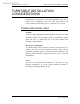
Archived 3/31/10 MODEL 2088 ELECTRIC POWERED TURNTABLE Electrical Installation ELECTRICAL INSTALLATION CAUTION: Electrical connection should only be performed by a qualified electrician and subject to local electrical codes. The Model 2088 is designed to operate using 208-230 VAC singlephase 50 or 60Hz power. The branch circuit supplying power to the motor base should be protected from excess current according to local electrical codes.
Archived 3/31/10 Electrical Installation MODEL 2088 ELECTRIC POWERED TURNTABLE Next you will need to make a cut down the length of sheath area, being careful not to cut into fiber cable. You should see two pieces of white string inside the sheath. Find the string and use it to split the sheath open. Now insert into the waveguide. 14 © ETS-LINDGREN L.P.
Archived 3/31/10 MODEL 2088 ELECTRIC POWERED TURNTABLE Operation OPERATION Please refer to the Model 2090 Positioning Controller manual if you are unfamiliar with the operation of the unit. A 2090 manual is included with each 2090 shipment and is also available for download from our website www.ets-lindgren.com . With the assembly complete the Model 2090 controller will need to be connected to the unit and power applied to both the motor base and controller in order to continue.
Archived 3/31/10 Operation MODEL 2088 ELECTRIC POWERED TURNTABLE EDITING MODEL 2090 POSITIONING CONTROLLER CONFIGURATION PARAMETERS To edit a configuration parameter, press the PARAM key to display the current parameter. Pressing the PARAM key repeatedly will scroll down through the parameter list, showing each parameter in turn. While viewing a parameter, the STEP keys (INC/DEC) may be used to scroll up or down the parameter list.
Archived 3/31/10 MODEL 2088 ELECTRIC POWERED TURNTABLE Operation DECRM keys under LIMIT until the desired limit is shown on the display. Press the ENTER key. WARNING: Ensure the current travel limit settings will not cause damage to existing cables and equipment located underneath the turntable. Should continuous operation be desired, the Model 2090 Controller permits easy configuration to this type of operation from the front panel or through the IEEE-488 interface bus.
Archived 3/31/10 Operation MODEL 2088 ELECTRIC POWERED TURNTABLE 5. Record the reading of the display, ignoring the decimal point (i.e. 360.0 would be 3600). This is the encoder calibration value. NOTE: If the value is below 3600, the resolution of the encoder is low and thus the 2090 will not provide 0.1 degree resolution, even though the display shows that digit. If the value has gone past 9999, the encoder has too many counts per meter and the 2090 can not correct for it.
Archived 3/31/10 MODEL 2088 ELECTRIC POWERED TURNTABLE Operation Then the “current position” button is pressed to get back to operation mode. The table is rotated from 0 to 360 and the mark is now within one degree of being one full turntable revolution. Calibration is complete. SETTING CURRENT POSITION ON 2090 The Model 2088 Turntable is not equipped with mechanically actuated or “hard” limit switches. The stopped position of the turntable platform at 0 degrees may drift overtime depending on usage.
Archived 3/31/10 Operation MODEL 2088 ELECTRIC POWERED TURNTABLE have this or a later revision installed, consult the factory for an upgrade. To select one of the four speeds, use the POLAR/SPEED button to toggle through the speed options. It is necessary to set the Model 2090 parameters to configure the controller to properly control the motor base. Refer to the Model 2090 Manual to the section which describes setting the parameters.
Archived 3/31/10 MODEL 2088 ELECTRIC POWERED TURNTABLE Operation change to the next speed setting. The polarization LEDs will light to indicate the speed selection in a binary fashion as shown below: Speed 1: Both off Speed 2: Top on, bottom off Speed 3: Top off, bottom on Speed 4: Both on Each speed setting has its own individual overshoot compensation value to provide proper overshoot correction for each speed selection.
Archived 3/31/10 Hand Control Unit MODEL 2088 ELECTRIC POWERED TURNTABLE HAND CONTROL UNIT To connect the Hand Control Unit (HCU), remove the connector cap on the motor base. Plug the cable receptacle from the hand control unit into the electrical enclosure and screw connectors completely together. The HCU is now ready to operate. Be sure to coordinate use of the unit with the operator of the Model 2090 Positioning Controller.
Archived 3/31/10 MODEL 2088 ELECTRIC POWERED TURNTABLE Recommended Maintenance RECOMMENDED MAINTENANCE CAUTION: Do not perform maintenance while turntable is operating. Disconnect the power connection for safety. Regular maintenance will prolong the serviceable life of your turntable. Follow this recommended schedule. EVERY SIX MONTHS Grease the casters. Use a good quality bearing grease to lubricate the casters. Inspect the ground brush for contaminates. Vacuum the brush to remove unwanted debris.
Archived 3/31/10 Specifications MODEL 2088 ELECTRIC POWERED TURNTABLE SPECIFICATIONS ELECTRICAL Nominal AC Voltage Input Frequency Phase AMP RPM 230 VAC 50/60 Hz Single Phase 2.0 0.5/2.0 variable MECHANICAL Diameter Height Distributed Load Rating* 1.2 meter 14.8 cm (5.8 in) 500 kg (1100 lb) 1.53 meter 14.8 cm (5.8 in) 1000 kg (2200 lb) 2.03 meter 14.8 cm (5.8 in) 1000 kg (2200 lb) *Distributed Load Rating is based on load being evenly distributed to each section. No point loads under 0.37 sq.
Archived 3/31/10 MODEL 2088 ELECTRIC POWERED TURNTABLE Warranty Statement WARRANTY STATEMENT ETS-Lindgren L.P., hereinafter referred to as the Seller, warrants that standard EMCO products are free from defect in materials and workmanship for a period of two (2) years from date of shipment.
Archived 3/31/10 Illustrations MODEL 2088 ELECTRIC POWERED TURNTABLE ILLUSTRATIONS See assembly drawings on following pages. 26 © ETS-LINDGREN L.P.
Archived 3/31/10
Archived 3/31/10
Archived 3/31/10
Archived 3/31/10
Archived 3/31/10
Archived 3/31/10
Archived 3/31/10
Archived 3/31/10
Archived 3/31/10
Archived 3/31/10
Archived 3/31/10
Archived 3/31/10